


Performance Check and Calibration Procedures
TPG20 Service
1–15
c. Check – WFM601i for correct video signal display. Repeat check for
the second TPG20 SERIAL DIGITAL OUTPUT.
19. Check PAL 625/50 Component Digital Serial
a. Set TPG20:
FORMAT 625/50 COMPONENT D1/YPrPb
Groups: BARS; EBU COLOR BARS 625 D1/YPrPb
b. Connect one of the TPG20 SERIAL DIGITAL OUTPUTs to the
WFM601i.
c. Check – WFM601i for correct video signal display. Repeat check for
the second TPG20 SERIAL DIGITAL OUT.
20. Serial Signal Integrity
a. Connect TPG20 SERIAL DIGITAL OUTPUT to the WFM 601i, using a
75W cable. Terminate the loop through in 75W.
b. Check – that the SERIAL DIGITAL OUTPUT amplitude is 800 mV
±10%.
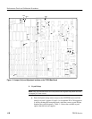
c. Adjust the WFM 601i Variable Vertical Gain so that the eye pattern
display is 10 divisions in height.
d. Check – that the rise time and fall time are > 0.75 ns and < 1.5 ns
(20% to 80%).
e. Check – that any overshoot is less than 10%.
21. Input/Output Return Loss: >36 dB up to 4.5 MHz
NOTE. The Return Loss Check only needs to be done if repairs have been made
on the Input circuitry.
a. Set TPG20:
FORMAT 525/60 COMPONENT YPrPb
Groups: FLAT FIELDS; BLACK 525 YPrPb
b. Connect a precision 50 W cable to the spectrum analyzer RF Input, and
another precision 50 W cable to the tracking generator output.
c. Connect the tracking generator Output cable to the RF Input on the RF
Bridge.