Performance Check and Calibration Procedures
1–20
TPG20 Service
RV1
N64
RN1
LV11
L10
TP5
D4
L9
TPE2
RV12RV13
RV14
TP7
TP16
TP15
TP14TP13
TP17
TPE1
TPE3
TPE6
TP4
TP9
TP8
TP1
TP2
TPE4
TP10
TP11
TP12
TP3
LK4
LK6
LK3
LK5
LK2
L19
LK9
LV10
RV9RV8
RV4RV5
LK8
LK7
L4
LK1
RV3
RV2
N59
TPE5
RV10
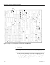
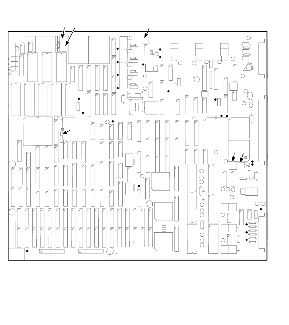
Figure 1–3: Jumper (Link) and Adjustment locations on the TPG20 Main Board
4. Crystal Setup
NOTE. This step should not be necessary unless the original setup data has been
corrupted for some reason.
a. Enter the System setup menus and press the SYSTEM button until the
setup for crystal 1 appears. Crystals 1 to 6 represent X3 to X8 respective-
ly and by rotating the front panel knob, select the correct crystal ID that
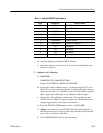
matches the crystal frequency. Table 1–1 shows the available crystal
options that the unit can support.


