


Performance Check and Calibration Procedures
1–10
TPG20 Service
b. Test both B Analog Outputs on the TPG20 using the VM700A DGDP
measurement mode. Differential Gain < 0.75% Differential Phase < 0.5°.
c. Set TPG20:
FORMAT 525/60 COMPOSITE NTSC/D2
Groups: LINEARITY; MODULATED RAMP 525 NTSC/D2
d. Test both B Analog Outputs on the TPG20 using the VM700A DGDP
measurement mode. Differential Gain < 0.75% Differential Phase < 0.5°.
7. Trigger Line Select – Trigger Out
a. Set TPG20:
FORMAT 525/60 COMPOSITE NTSC/D2
Groups: BARS: SMPTE COLOR BARS 525 NTSC/D2
b. Use the oscilloscope to check for a negative going field rate pulse of
w0.5 V into 75 W, from the TPG20 TRIGGER OUT connector.
c. Look at the TPG20 composite video output (A Analog Output) with the
oscilloscope externally triggered by the TPG20 TRIGGER OUT signal.
d. Press the TPG20 TRIGGER button. Use the TPG20 knob to select the
line to be viewed on the oscilloscope. Verify correct operation by
looking for video signals on lines 17, 18, 280 and 281 (VITS). Check
both frames 1 and 2.
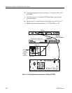
8. Genlock NTSC – Horizontal Phase Adjustment ±one half line.
a. Connect the TSG170A Black Burst signal to the TPG20 REFERENCE
INPUT. Connect the other side of the REFERENCE INPUT loop-
through to CH 1 on the oscilloscope (terminated into 75 W).
b. Connect one of the Analog B Outputs of the TPG20 to CH 2 of the
oscilloscope.
c. Trigger the oscilloscope internally on the CH 1 signal.
d. Set TPG20:
FORMAT 525/60 COMPOSITE NTSC/D2
Groups: BARS; SMPTE COLOR BARS 525 NTSC/D2
e. Set TPG20: Genlock to On. Select Lock on: Sync Lock. Verify that
genlock occurs within 20 seconds and the Genlock light is on (not
blinking).