


Performance Check and Calibration Procedures
TPG20 Service
1–13
Group: BARS; EBU COLOR BARS 625 PAL/D2
Set: D2 Output Serial
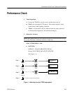
b. Connect TPG20 SERIAL DIGITAL OUTPUT to 1731D Serial Input and
1731D DAC Out to the 1781, which is set to Video Monitor display.
Terminate the loop–through in 75W
c. Check – for correct video signal display on 1731D and 1781.
d. Move the cable to the second TPG20 SERIAL DIGITAL OUTPUT and
repeat part c.
e. Set TPG20:
PATTERN – Groups: LINEARITY; RAMP 100% 626 PAL/D2
f. Check – for correct video signal display on 1731D and 1781.
g. Return cable to the first TPG20 Serial Output and repeat part f.
15. Check Parallel Digital Output PAL D2
a. Set TPG20:
FORMAT 625/50 COMPOSITE PAL/D2
Groups: LINEARITY; RAMP 100% 625 PAL/D2
Set: D2 Output Parallel
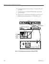
b. Connect TPG20 PARALLEL DIGITAL OUTPUT to 1731D Parallel
Digital Input.
c. Check – for correct video signal display on 1731D and 1781.
d. Set TPG20:
FORMAT 625/50 COMPOSITE PAL/D2
Groups: BARS; EBU COLOR BARS 625 PAL/D2
e. Check – for correct video signal display on 1731D and 1781.
16. Check Serial Digital Outputs NTSC D2
a. Set TPG20:
FORMAT 525/60 COMPOSITE NTSC/D2
Groups: BARS; SMPTE COLOR BARS 525 NTSC/D2
Set: D2 Output Serial