


ADCP-75-192 • Issue 2 • June 2007
Page 4
© 2007, ADC Telecommunications, Inc.
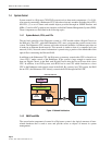
1.4 System Control
System control in a Digivance CXD/NXD system involves three main components: (1) a LAN-
type network connecting a Hubmaster CPU with other electronic modules including slave CPUs
and FICs; (2) a set of alarms and settable objects provided through an SNMP interface and
MIBs; (3) and an ADC graphical user interface called the Element Management System (EMS).
These components are described in the following topics.
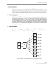
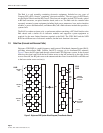
1.4.1 System Network, CPUs, and FICs
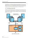
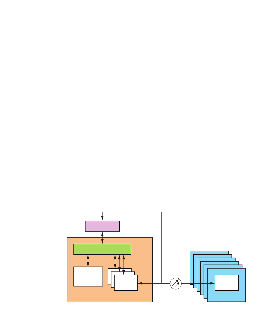
The top-level controller of the Digivance system is a CPU module within a Digital Chassis on
the Hub rack. This CPU, called the Hubmaster CPU, runs a program that controls events in the
system. The Hubmaster CPU connects with other electronic modules via Ethernet ports that act
as nodes in an Ethernet-based network. This network is similar to that of a computer local area
network (LAN). Network control information is passed using a portion of the bandwidth of the
optical fibers connecting the Hub and RAN.
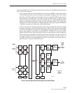
In addition to the Hubmaster CPU, the Digivance system may contain other CPUs referred to as
“slave CPUs” under control of the Hubmaster. If the system is large enough to require more
than one Digital Chassis in the Hub, each Digital Chassis after the first will have such a slave
CPU. In addition, in an NXD system, each RAN has its own CPU which functions as a slave
CPU to the Hubmaster and controls events in the RAN. By contrast, in a CXD system, the RAN
has no CPU; the Hubmaster CPU directly controls the RAN through the RAN FIC
Figure 4. Network Architecture
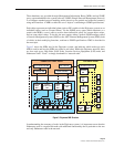
1.4.2 SNMP and MIBs
The second main component of control in a Digivance system is the logical structure of inter-
related databases that is used to store and provide access to objects of interest in system
management.
21946-A
HUB
HUB
MASTER
HUB
NODE
RAN
RAN
NODE
CAT5
ETHERNET
ETHERNET HUB
ROUTER
EXISTING WAN/LAN
FIBER