


ADCP-75-192 • Issue 2 • June 2007
Page 14
© 2007, ADC Telecommunications, Inc.
2 NETWORK CONFIGURATION DETAILS
This section provides details on items that are important to understand when configuring the
Digivance system.
2.1 Node and Equipment Identification
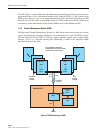
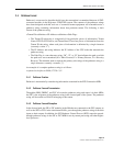
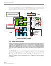
In the Digivance CXD/NXD system, a “node” is a hardware focus of activity. The main Hub
CPU (the system’s Master CPU) and the RANs are each a separate node. They are referred to as
the “Hubmaster Node” and “RAN Nodes.” In a large system, there may be additional CPUs at
the Hub. These CPUs are configured as Slave CPUs and are referred to as “Hub Nodes.” RAN
Nodes are Slave CPUs (in an NXD system) or FICs (in a CXD system) located in a RAN
cabinet. “Equipment” in a CXD/NXD system is comprised of functionally separate items such
as chassis and electronic modules that each have a predetermined physical location on a Hub
rack or within a RAN cabinet.
2.1.1 Identification Using the Network IP Receiver/Sender System
The Hubmaster Node dynamically keeps track of which nodes are under its control using a
script called NIPR (Network IP Receiver). The Hubmaster Node receives an IP and hostname
from every node it controls via NIPS (Network IP Sender), which runs on all “slave” nodes.
NIPR senses any changes to its list of slave nodes, and updates the Hubmaster DNS
accordingly. The NIPR/S system is also a key component to maintaining the Hub/RAN Node
MIBs and tenant processing, since it is the mechanism by which the Hub/RAN Node MIB
entries are filled. For more on these MIBs, see Section 3.8 on Page 39.
2.1.2 Node Identification Schemes
It is important to follow a convention when naming nodes in the Digivance system so that the
nodes can be quickly located and accessed for troubleshooting and maintenance. The suggested
naming conventions for both Hub and RAN nodes are discussed in the following topics. For
more information concerning node identity configuration, refer to Section 3.8 on Page 39.
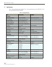
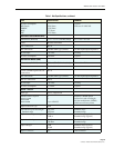
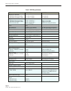
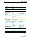
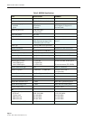
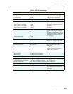
2.1.3 Hub Equipment Identifications
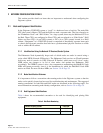
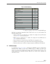
Table 4 shows the recommended convention to be used for identifying and placing Hub
equipment:
Table 4. Hub Rack Numbering
CHASSIS OR SHELF HEIGHT
LOCATION*
Attenuator Shelf 2U U42
PDU 2U U40