


ADCP-75-192 • Issue 2 • June 2007
Page 13
© 2007, ADC Telecommunications, Inc.
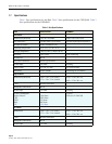
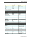
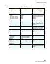
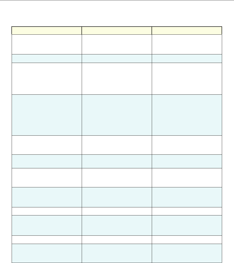
Receiver noise figure
PCS band
Cellular band
6 dB
5 dB
Measured at Hub output connec-
tor (BIM, RxP) without BTS at 10
dB gain and a single RAN
Input IP3 -21 dBm Two tone tests at -56 dBm
Received signals
In band
Out of band +/- 8.5 MHz
Out of band +11/-13 MHz
Out of band +13/-16 MHz
-41 dBm
-3 dB
-43 dB
-83 dB
RDC capability (at cabinet input)
A/D clip level, single RF channel
Selectivity
(function of SAW filter)
Selectivity
Selectivity
Automatic gain control
Gain control range
30 dB
Activated if A/D clips, changes
gain of A/D and gain in digits.
Design ensures analog gain and
digital gain change will be timed
correctly. 15 dB noise figure at
-14 dB gain
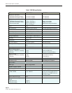
Gain in series with BTS -10 to +10 dB Lower limit for simulcast with a
host tower site, the max reduces
effect of cascaded noise figure
Gain parallel to BTS 0 to +30 dB Allows injection after BTS
amplifiers
Gain stability +/- 2dB Over temperature, frequency, and
aging valid for input signals
below AGC threshold
System Bandwidth
Forward Path
Reverse Path
15 MHz block increments
15 MHz block increments
Impedance 50 ohm
Output Power
Cellular/SMR 10 Watt MCPA
PCS 20 Watt MCPA
6.5 Watts (+38 dBm) composite
12.5 Watts (+41 dBm) composite
At antenna port
At antenna port
Gain resolution 1 dB
Gain measurement Configured at startup using fac-
tory calibration of modules and
user data
Table 3. NXD RAN Specifications
ITEM SPECIFICATION COMMENT