


ADCP-75-192 • Issue 2 • June 2007
Page 17
© 2007, ADC Telecommunications, Inc.
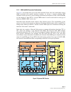
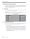
2.2.2 MIB Hub/RAN Connection Relationships
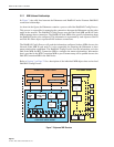
In Figure 8, the dashed lines seen in the Hub and RAN Nodes show the relationships among
MIBs associated with specific hardware modules. As shown, a separate software HCP
(hardware control process) is used to manage each hardware module in a node. The HCP MIBs
are the interface to these HCPs. A single MIB instance is used in each node for each type of
hardware (FBHDC, RDC, and so on).
Each Hub Node and RAN Node contains a Bus Scanner process. The responsibility of this
process is to discover the presence or absence of hardware modules and to start or stop HCPs to
manage those hardware modules. The Bus Scanner MIB reports the information defining the
hardware “discovered” at that node.
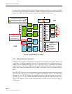
Each node also contains a Network Node process to manage information about that CPU or
FIC, where the interface is the Network Node MIB. The Network Node MIB contains
information about the CPU or FIC itself (for example, IP Address, Hostname, and so on), Hub/
RAN specific information (for example, Pole ID, RAN Box ID, and so on), and other
miscellaneous status information. In addition, the Network Node MIB reports a high-level fault
status for each HCP type. If any HCP in that node reports a fault of any type in its HCP MIB,
the Network Node MIB fault field corresponding to that HCP will report a problem.
Figure 8. Digivance MIB Structure
HUBMASTER SNMP AGENT RAN SNMP AGENT
HUB NODE SNMP AGENT
BTS CONNECTION MIB NETWORK NODE MIB
HUB NODE MIB
RAN NODE MIB
TENENT OAM MIB
HUB RF
CONNECTION
MIB
NETWORK
NODE
MIB
NODE
PATH
MIB
NODE
PATH
MIB
EQUIPMENT
MIB
EQUIPMENT
MIB
PATHTRACE
MIB
NODE
PATH
MIB
BIM
MIB
HDC
MIB
HUC
MIB
FSC
MIB
RSC
MIB
SIF/
FIC
MIB
STF
MIB
HRM
MIB
MUC
MIB
*STF
MIB
GPS
MIB
RDC
MIB
RUC
MIB
GPS
MIB
BACK-
PLANE
MIB
BACK-
PLANE
MIB
POWER
ENTRY
MIB
21943-A
SIF/
FIC
MIB
*NXD
ONLY