


ADCP-75-192 • Issue 2 • June 2007
Page 7
© 2007, ADC Telecommunications, Inc.
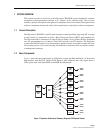
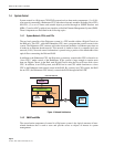
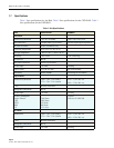
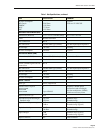
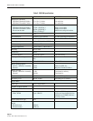
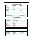
All CPUs in the Digivance network support SNMP to provide NMS monitoring and access. The
NMS software (whether generic or EMS) sends SNMP GET and SET messages to the various
nodes in the Digivance network to access MIBs in response to a user entry.
• A GET message gets the current value of an identified object.
• A SET message sets the object to a given value. Only a limited subset of objects can be set
to a new value.
The EMS is resident on the Hubmaster CPU and is accessible through an Ethernet connection.
Operation is effected through the EMS Graphical User Interface (GUI). The GUI consists of a
series of screens from which the user selects the desired option or function. Ethernet ports are
available at the Hub and RAN CPU for connecting the EMS computer at either location
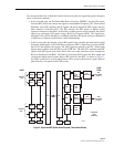
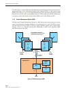
1.5 Fiber Optical Transport
The optical signal of a Digivance system is digital. The input and output RF signal levels at the
Hub FIC or the RAN FIC or SIF are not dependent on the level of the optical signal or the
length of the optical fiber.
The maximum length of the optical fibers is dependent on the loss specifications of the optical
fiber and the losses imposed by the various connectors and splices. The system provides an
optical budget of 9 dB (typical) when used with 9/125 single-mode fiber, or 26 dB with
extended optics.
The optical wavelengths used in the system are 1310 nm for the forward path and 1310 nm for
the reverse path. Different wavelengths may be used for the forward and reverse paths allowing
for a pair of bi-directional wavelength division multiplexers (WDM) or coarse wavelength
division multiplexing (CWDM) to be used in applications where it is desirable to combine the
forward path and reverse path optical signals on a single optical fiber.
One WDM or CWDM multiplexer/demultiplxer module may be mounted with the Hub and the
other mounted with the RAN. The WDM or CWDM passive multiplexers are available as
accessory items.
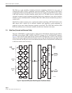
1.6 Fault Detection and Alarm Reporting
LED indicators are provided on each of the respective modules populating the Hub Digital
Chassis, RF Chassis, and RAN Chassis to indicate if the system is normal or if a fault is
detected. In addition, a dry contact alarm interface can be provided as an accessory item that is
managed by the EMS software with normally open and normally closed alarm contacts for
connection to a customer-provided external alarm system.
All Hub and RAN alarms can be accessed through the SNMP manager or the EMS software
GUI.
Note: MIBs are described in more detail in Section 2.2 on Page 15.