


ADCP-75-192 • Issue 2 • June 2007
Page 15
© 2007, ADC Telecommunications, Inc.
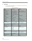
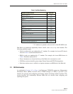
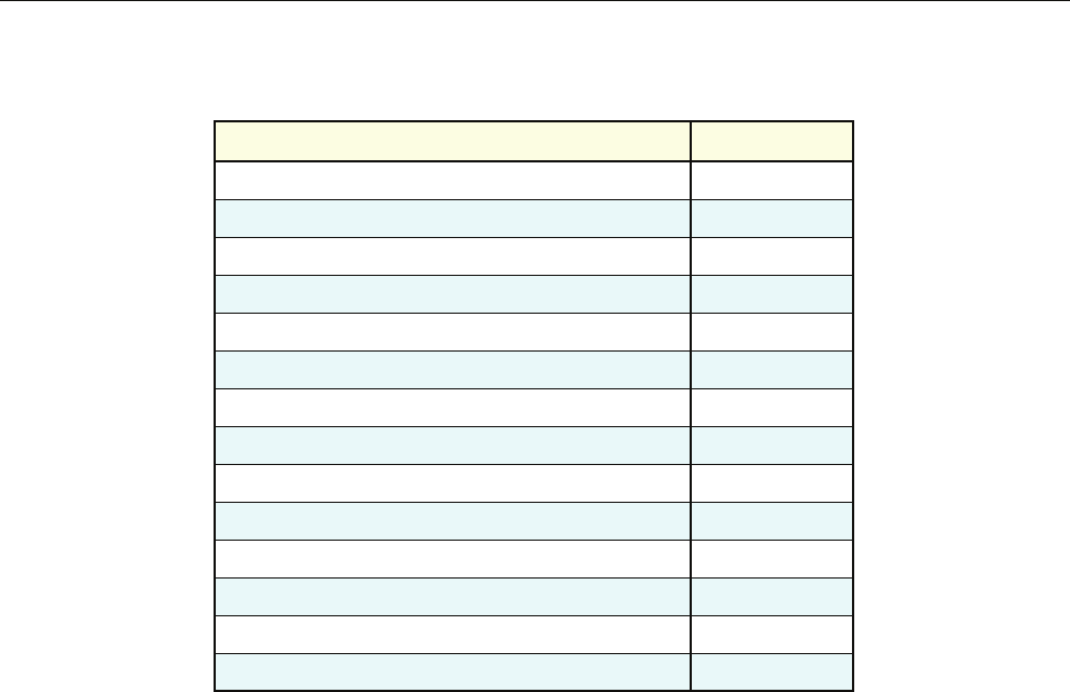
*’U’ numbers are printed on the rack rails of the OP-HUB2 rack.
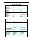
Hub Racks are numbered sequentially: Rack1, Rack2, and so on, or by serial number. The
following guidelines apply:
• Chassis in Hub racks are numbered by ‘U’ number. For example, the lowest RF chassis
shown in Table 4 would be numbered U12.
• BIMs in racks are numbered by ‘U’ number. For example, the lowest BIM shown in
Table 4 Would be numbered U8.
• Power Attenuators are located at the top of the Hub rack or mounted to a wall.
• WSP Base stations should be given unique Tenant Name and BTS ID designations.
• Each base station sector is cabled to a separate attenuator and BIM unit in the Hub rack.
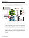
2.2 MIB Relationships
As explained in Section 1.4.2 on Page 4, the Digivance CXD/NXD system uses Management
Information Bases (MIBs) accessed with an SNMP manager (or EMS) to provide a user
interface for querying and configuring perrformace objects and being notified of alarms. This
section describes the relationships between MIBs that are relevant when cofiguring and
operating the system.
Ethernet Hub 1U U38
Digital Chassis (top) 4U U37
BIM 1U U33
RF Chassis (top) 4U U32
BIM 1U U28
Digital Chassis (top) 4U U27
BIM 1U U23
RF Chassis (top) 4U U22
BIM 1U U18
Digital Chassis (top) 4U U17
BIM 1U U13
RF Chassis (top) 4U U12
BIM 1U U8
Reference Module (bottom) 1U U7
Table 4. Hub Rack Numbering
CHASSIS OR SHELF HEIGHT
LOCATION*