


ADCP-75-192 • Issue 2 • June 2007
Page 27
© 2007, ADC Telecommunications, Inc.
3.3.2.7 HUC Invalid Config
The BTS Connection MIB contains a read-only field that reports the state of the HUC Invalid
Configuration fault field. This information will allow the person configuring the system to know
that the tenant has been completely and correctly configured - this is known when the value in
this field is reported as “No Fault” or '0'. The MIB field is:
transceptBtsConnectionTable.transceptBtsConnectionHucInvalidConnection.
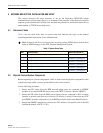
3.3.2.8 Composite Mode
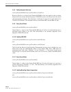
The Digivance CXD/NXD default forward gain balance is called “composite mode.” In this
mode, a composite RF signal will have gain of +42dB (Cell/SMR) and +45dBm (PCS) through
the system. The maintainer is responsible for ensuring the desired signal level into the system.
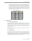
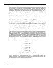
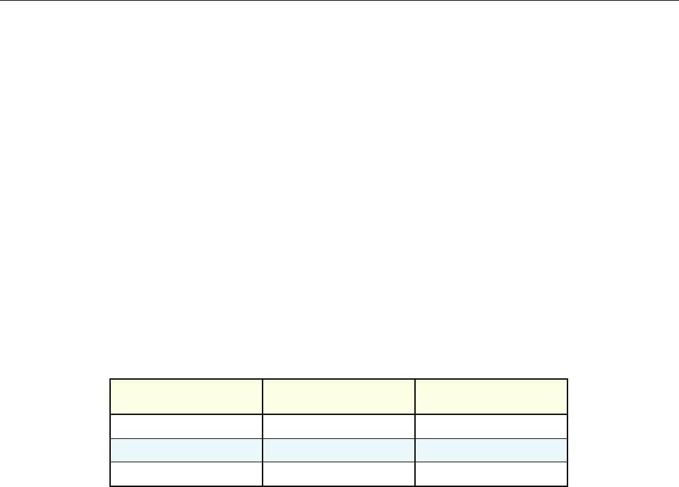
See Table 3-3 for sample input and output signal strengths:
As the protocol is irrelevant in this mode, the default protocol is “none”. In addition, only a
single FSC channel is activated. To sum multiple FSC channels, set the composite mode entry to
“disabled” and follow instructions on setting channels in Section 7 Tenant Configuration. The
MIB field is:
transceptBtsConnectionForwardGainTable.transceptBtsConnectionForwardGainCompositeMo
deFlag
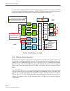
3.3.2.9 Power Attenuator IDs
The BTS Connection MIB contains two fields that allow the external power attenuators to be
identified. The attenuators reside in a shelf at the top of each rack. To configure these two MIB
fields, the nomenclature described in 3-1. HUB Rack Numbering, should be used. This dictates
that the attenuators should be given names that indicate the shelf number and the location on the
shelf. For a given tenant, the two power attenuators must be configured with unique IDs, where
the allowable values are strings of length 1-16. If both attenuators are configured, then software
will configure the BIM to operate in duplexed mode, otherwise, software will configure the
BIM to operate in non-duplex mode. The MIB fields are:
transceptBtsControlParamsTable.transceptBtsControlParamsPowerAttenXLoc,
where X = 1 or 2.
Table 7. Output Signal Strength
INPUT
(RMS AT FBHDC INPUT)
CELL/SMR OUTPUT
(RMS AT ANTENNA PORT)
PCS OUTPUT
(RMS AT ANTENNA PORT)
-2 dBm +40 dBm +43 dBm
-4 dBm +38 dBm +41 dBm
-7 dBm +35 dBm +38 dBm