18 en | Connections and settings Digital Video Recorder
F01U | 2.0 | 2008.12 User Manual Bosch Security Systems
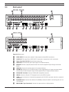
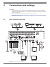
a Connect the cameras to the BNC loop-through camera inputs (automatically terminated).
b Connect the Monitor, DVR, VCR, or others to the video out BNC.
c Connect the power cord to the unit.
d Connect an audio amplifi er.
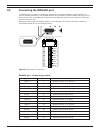
e Connect a pan/tilt/zoom control unit via the supplied 15-pole D-type connector board.
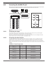
f Connect up to 16 (alarm) inputs or connect up to 8 alarm output relays via the supplied 25-pin
D-type connector board.
g Connect PTZ cameras or DVRs.
h Connect a Bosch CCTV keyboard unit to the KBD IN socket.
i Connect audio (line input).
j Connect to your network via the Ethernet port or use the RS232 connector to connect directly
to a PC serial port (for service purposes).
k Connect monitor B to the BNC output MON B.
l Connect monitor A to the BNC output MON A.
m Connect a VGA monitor.
n Connect optional extension USB devices (e.g. mouse, memory stick).
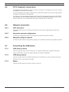
3.2 Camera connections
Connect cameras to the unit using 75-ohm video coaxial cables with BNC connectors. There are
two BNC connectors for each camera. Either connector can receive a camera’s signal. This signal
is looped-through (directly connected) to the other connector, so that you can send the camera’s
signal to other equipment. The camera input connectors are auto-terminating, so you do not need to
add a terminator to the output connector if no additional equipment is connected.
If the camera signal is looped-through to additional equipment, make sure that the end of the video
line is terminated with a 75-ohm terminator.
3.3 Monitor connections
Connect the unit to the monitors via 75-ohm video coaxial cables with BNC connectors. The unit
provides a 1Vpp CVBS signal.
If the monitor has a loop-through connection and you are not using the loopthrough output, then
select the 75-ohm impedance setting on the monitor. If the monitor’s loop-through output is
connected to an additional device, the device’s termination is set to 75 ohms and the monitor’s
termination is set to high impedance (note that this is not necessary on devices with automatic
termination).
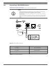
3.4 Connecting the RS-232C (COM 1) Port
The serial RS232 console port connector is used to connect a PC to the unit for service purposes.
Use a null-modem cable to connect the serial port of the PC to the unit.
This terminal is compliant with the RS-232C standard.


