


Stand-alone DVR Instruction Manual
26
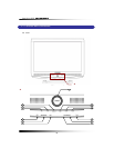
(screen) as shown [Fig.5-4-2].
- Attach the mounting bracket to the desired location on the wall. Locate wall studs and
securely fix the mounting bracket with the supplied screws.
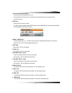
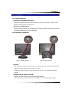
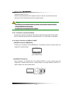
5-4.2.1. Connection of Composite Monitor
If necessary, connect the composite Video Output (yellow RCA) and Audio Output (white
RCA) to Video IN and Audio IN on a composite monitor or TV (RCA cable: not included).
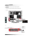
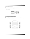
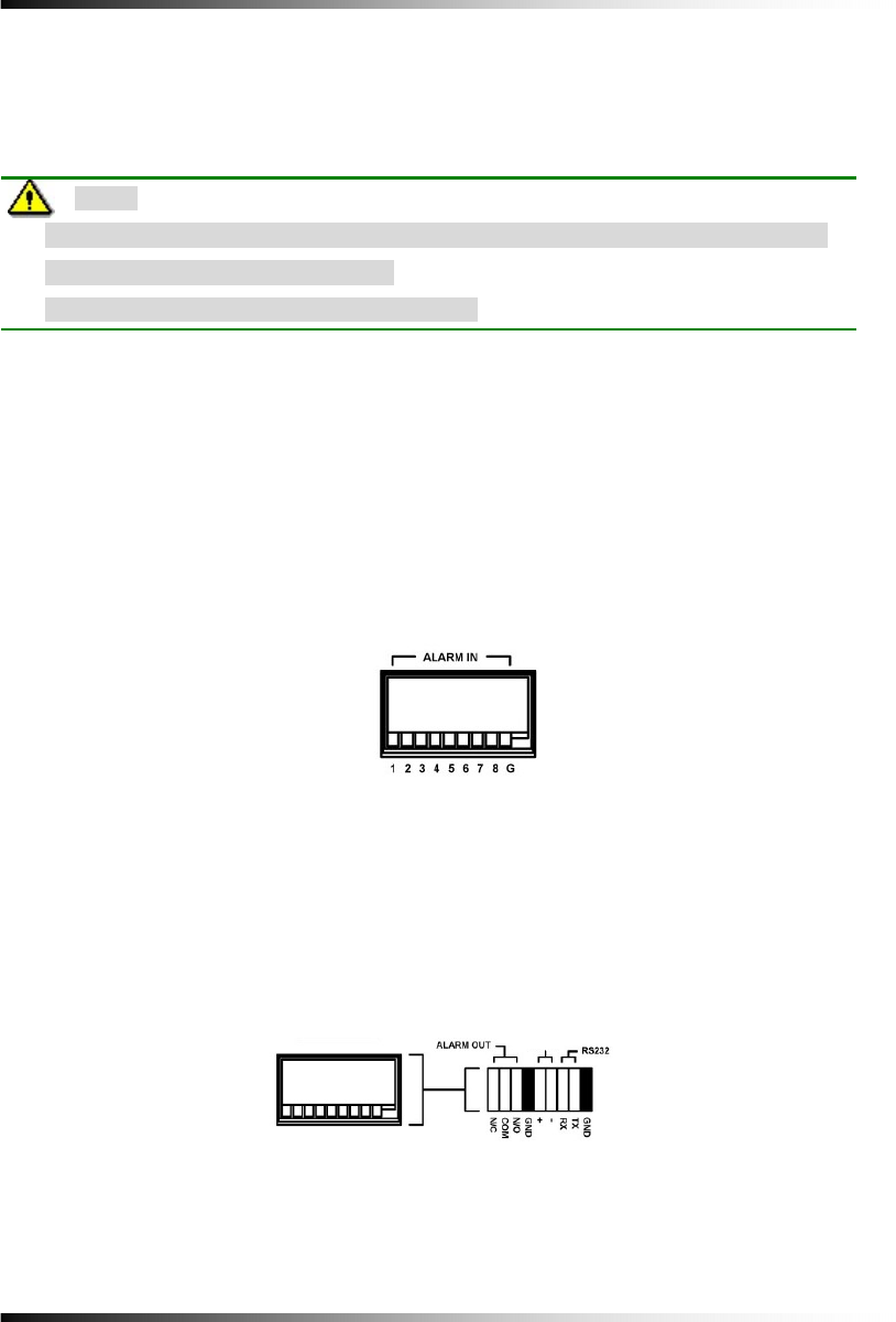
5-4.3. Sensor Connection and RELAY IN &OUT
▫ SENSOR Connection (SENSOR IN)
Connect up to 8 sensors to ALM (SENSOR) IN. The Sensors should be contactor type and
support N.O. (Normal Open).
[Fig 5-5 SENSOR IN PIN]
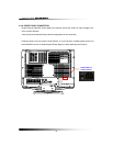
▫ ALARM OUT Connection
When necessary, use ALARM OUT. The ALARM OUTPUT is a relay contactor type and
supports N.O. (Normal Open) and N.C. (Normal Close). The Output capacity is 220V 1A. A
higher capacity can cause system failure.
[Fig 5-5]
Note:
- Pay attention to not make scratches or dents on the surface of panel (screen)
during installation of the system.
- In case of this, the warranty will be voided.
RS-485
[Fig 5-6 Alarm Output]