


392.1. Scope.
Of the types of cable trays listed in this section,
ladder cable tray is the most widely used type of
cable tray due to several very desirable features.
• The rungs provide a convenient anchor for
tying down cables in vertical runs or where the
positions of the cables must be maintained in
horizontal runs.
• Cables may exit or enter through the top or the
bottom of the tray.
•A ladder cable tray without covers provides for
the maximum free flow of air, dissipating heat
produced in current carrying conductors.
• Moisture cannot accumulate in ladder cable
trays and be piped into electrical equipment as
happens in conduit systems.
• Ladder cable tray cannot pipe hazardous or
explosive gasses from one area to another as
happens with conduit systems.
• In areas where there is the potential for dust to
accumulate, ladder cable trays should be installed.
The dust buildup in ladder cable trays will be less
than the dust buildup in ventilated trough or solid
bottom cable trays.
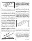
Ladder cable trays are available in widths of 6, 9,
12, 18, 24, 30, 36, and 42 inches with rung
spacings of 6, 9, 12, or 18 inches. Wider rung
spacings and wider cable tray widths decrease the
overall strength of the cable tray. Specifiers should
be aware that some cable tray manufacturers do not
account for this load reduction in their published
cable tray load charts. B-Line uses stronger rungs in
wider cable trays to safely bear the loads published.
With one exception, the specifier selects the rung
spacing that he or she feels is the most desirable for
the installation. The exception is that 9 inches is the
maximum allowable rung spacing for a ladder cable
tray supporting any 1/0 through 4/0 single
conductor cables
[See Section 392.3(B)(1)(a)].
Where the ladder cable tray supports small
diameter multiconductor control and
instrumentation cables; 6, 9, or 12 inch rung
spacings should be specified. Quality Type TC,
Type PLTC, or Type ITC small diameter
multiconductor control and instrumentation cables
will not be damaged due to the cable tray rung
spacing selected, but the installation may not appear
neat if there is significant drooping of the cables
between the rungs.
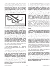
For ladder cable trays supporting large power
cables, 9 inch or wider rung spacings should be
selected. For many installations, the cable trays are
routed over the top of a motor control center (MCC)
or switchgear enclosure. Cables exit out the bottom
of the cable trays and into the top of the MCC or
switchgear enclosure. For these installations, the
cable manufacturer's recommended minimum
bending radii for the specific cables must not be
violated. If the rung spacing is too close, it may be
necessary to remove some rungs in order to
maintain the proper cable bending radii. This
construction site modification can usually be avoided
by selecting a cable tray with 12 or 18 inch rung
spacing.
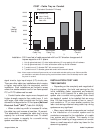
If you are still uncertain as to which rung spacing
to specify, 9 inch rung spacing is the most common
and is used on 80% of the ladder cable tray sold.
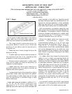
9
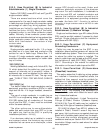
Standard Aluminum Ladder
AN IN-DEPTH LOOK AT 2002 NEC
®
ARTICLE 392 - CABLE TRAY
(The following code explanations are to be used with a copy of the 2002 NEC
®
.)
To obtain a copy of the NEC
®
contact:
National Fire Protection Association
®
1 Batterymarch Park • P.O. Box 9101
Quincy, Massachusetts 02269-9101
1-800-344-3555
Cable Tray Manual Cooper B-Line, Inc