


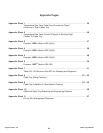

53
Cable Tray Manual Cooper B-Line, Inc
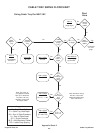
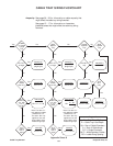
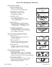
CABLE TRAY SIZING FLOWCHART
Appendix Sheet 8
392.9(E)(1)
W x D ≥ 1.6A
392.9(A)(1)
W ≥ Sd
(single layer)
392.9(C)(1)
W ≥ Sd/0.9
(single layer)
Note: The value “A”
only applies to cables
smaller than 4/0.
The value “Sd” only
applies to 4/0 and
larger cables, which
must be single layer
Note: The value “A”
only applies to cables
smaller than 4/0.
The value “Sd” only
applies to 4/0 and
larger cables, which
must be single layer
392.9(A)(3)
Vented
Channel
Tray
Solid
Channel
Tray
Solid
Bottom
Tray
Ladder
or Vented
Trough
Tray
One M/C
only
M/C 4/0
or larger
M/C 4/0
or larger
392.9(E)(2)
W x D ≥ 2.9A
392.9(F)(1)
W x D ≥ 1.9A
392.9(F)(2)
W x D ≥ 3.2A
392.9(A)(2)
W ≥ A/1.2
392.9(C)(2)
W ≥ A/0.9
M/C
smaller
than 4/0
One
M/C
Only
M/C
smaller
than 4/0
M/C
smaller than
4/0, with
4/0 or
larger
M/C
control
and/or
signal
W ≥ A/1.2 + Sd
No NoNo
NoNo
NoNo
No No No
392.9(B)
W x D ≥ 2A
392.9(C)(3)
A + Sd
0.9
M/C
smaller than
4/0, with
4/0 or
larger
M/C
control
and/or
signal
W ≥
392.9(D)
W x D ≥ 2.5A
YesYes
Yes NoYes
Yes
Yes
Yes
YesYes
Yes
Yes Yes Yes
Yes
Legend
W = Cable Tray Width
D = Cable Tray Load Depth
Sd = Sum of Cable Diameters
A = Sum of Cable Areas
S/C = Single Conductor
M/C = Multiconductor Cables
RS = Ladder Rung Spacing
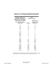
Ampacity: See pages 36 - 38 for information on cable ampacity that
might affect the cable tray sizing flowchart.
See pages 15 - 17 for information on hazardous
(classified) areas that might affect the cable tray sizing
flowchart.