


39
Cable Tray Manual Cooper B-Line, Inc
• Cable Tray Tag Numbers - The tagging system
should be developed by the design personnel with
identification numbers assigned to cable tray runs on
the layout drawings. Cable tray tag numbers are
used for controlling the installation of the proper
cable tray in the correct location, routing cables
through the tray system and controlling the cable fill
area requirements.
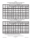
• Cable Schedules - A wire management system
is required for any size project. Cable schedules
must be developed to keep track of the cables. This
is especially true for projects involving more than
just a few feeder cables. A typical cable schedule
would contain most or all of the following:
• The Cable Number, the Cable Manufacturer &
Catalog Number, Number of conductors, the
conductor sizes, and the approximate cable length.
• Cable Origin Location - The origin equipment
ID with the compartment or circuit number and
terminals on which the cable conductors are to be
terminated. It should also include the origin
equipment layout drawing number, and the origin
equipment connection diagram number.
• Cable Routing - Identifies the cable tray sections
or runs that a cable will occupy. Cable tray ID tag
numbers are used to track the routing.
• Cable Termination Location - The device or
terminal equipment on which the cable conductors
are to be terminated. It should also include the
termination equipment layout drawing number, and
the termination equipment connection diagram
number.
Some design consultants and corporate
engineering departments use spread sheets to
monitor the cable tray runs for cable fill. With such a
program, the cable tray fill area values for each
cable tray run or section can be continuously
upgraded. If a specified cable tray run or section
becomes overfilled, it will be flagged for corrective
action by the designer.
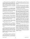
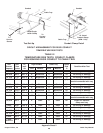
• Cable Installation Provisions - The cable tray
system must be designed and installed, to allow
access for cable installation. For many installations,
the cables may be hand laid into the cable trays and
no cable pulling equipment is required. There are
other installations where sufficient room must be
allotted for all the cable pulling activities and
equipment.
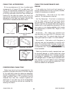
The cable manufacturers will provide installation
information for their cables such as maximum
pulling tension, allowable sidewall pressures,
minimum bending radii, maximum permissible
pulling length etc.. Lubricants are not normally used
on cables being installed in cable trays.
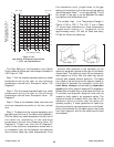
The engineer and designers should discuss in
detail the installation of the cables with the
appropriate construction personnel. This will help to
avoid installation problems and additional installation
costs. It is important that the cable pull is in the
direction that will result in the lowest tension on the
cables. Keep in mind there also needs to be room at
the ends of the pulls for the reel setups and for the
power pulling equipment. Cable pulleys should be
installed at each direction change. Triple pulleys
should be used for 90 degree horizontal bends and
all vertical bends. Single pulleys are adequate for
horizontal bends less than 90 degrees. Use rollers
in-between pulleys and every 10 to 20 feet
depending on the cable weight. Plastic jacketed
cables are easier to pull than are the metallic
jacketed cables and there is less chance of cable
damage. The pulling eye should always be attached
to the conductor material to avoid tensioning the
insulation. For interlocked armor cables, the
conductors and the armor both have to be attached
to the pulling eye.
Normally, the cables installed in cable trays are not
subjected to the damage suffered by insulated
conductors pulled into conduit. Depending on the
size of the insulated conductors and the conduit,
jamming can take place which places destructive
stresses on the cable insulation. In the October,
1991 issue of EC]&M magazine, the article on cable
pulling stated that 92 percent of the insulated
conductors that fail do so because they were
damaged in installation.