


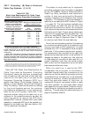

392.6. Installation. (C) Supports.
The intent of this section is to ensure that the
conductor insulation and cable jackets will not be
damaged due to stress caused by improper support.
Multiconductor 600 volt Type TC cables and 300
volt Type PLTC cables exhibit a high degree of
damage resistance when exposed to mechanical
abuse at normal temperatures.
During an inspection of industrial installations by
the 1973 NEC
®
Technical Subcommittee on Cable
Tray, a test setup was constructed of an 18 inch
wide Class 20C aluminum cable tray supported
three feet above ground level containing several
sizes of multiconductor cables. This installation was
continuously struck in the same area with eight
pound sledge hammers until the cable tray was
severely distorted, the cables however, exhibited
only cosmetic damage. When these cables were
tested electrically, they checked out as new tray
cable. Since that time, significant improvements
have been made in cable jacket and conductor
insulation materials so that the cables available today
are of better quality than the 1973 test cables.
Although tray cables are capable of taking a great
deal of abuse without any problems, cable tray
installations must be designed by taking appropriate
measures to ensure that the tray cables will not be
subjected to mechanical damage.
392.6. Installation. (D) Covers.
Cable tray covers provide protection for cables
where cable trays are subject to mechanical damage.
The most serious hazard to cable in cable trays is
when the cables are exposed to significant amounts
of hot metal spatter during construction or
maintenance from torch cutting of metal and
welding activities. For these exposure areas, the
cable tray should be temporarily covered with
plywood sheets. If such exposure is to be a frequent
occurrence, cable tray covers should be installed in
the potential exposure areas. Where cable trays
contain power and lighting conductors, raised or
ventilated covers are preferable to solid covers since
the raised or ventilated covers allow the cable heat
to be vented from the cable tray.
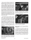
When covers are installed outdoors, they should
be attached to the cable trays with heavy duty wrap
around clamps instead of standard duty clips. During
high winds, the light duty clips are not capable of
restraining the covers. Outdoor cover installations
should be overlapped at expansion joint locations to
eliminate cover buckling. Covers which fly off the
cable tray create a serious hazard to personnel, as
was the case at a Texas gulf coast chemical plant
where operators would not leave their control room
because hurricane force winds had stripped many
light gauge stainless steel covers off a large cable
tray system. These sharp edged metal covers were
flying though the air all during the high wind period,
posing a serious threat to the worker's safety.
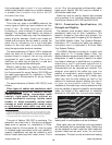
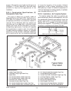
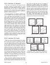
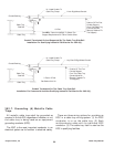
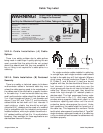
Types of Cable Tray Covers.
Aluminum Cable Tray Cover Accessories -
Equivalent Items are available for Steel Cable Trays.
23
Cable Tray Manual Cooper B-Line, Inc
Standard
Cover Clamp
Combination Cover
& Hold Down Clamp
Heavy Duty
Cover Clamp
Cover Joint Strip
Raised
Cover Clamp
Solid Non-Flanged Solid Flanged
Ventilated Flanged
Peaked Flanged