


support. Although the use of cable tray fittings is not
mandatory, it is often desirable to use them when
possible to improve the appearance of the
installation.
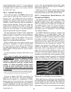
392.5. Construction Specifications. (F)
Nonmetallic Cable Tray.
This type of cable tray is usually made of
Fiberglass Reinforced Plastic (FRP). Applications for
FRP cable tray systems include some corrosive
atmospheres and where non-conductive material is
required. B-Line fiberglass cable tray systems are
manufactured from glass fiber reinforced plastic
shapes that meet ASTM flammability and self-
extinguishing requirements. A surface veil is applied
during pultrusion to ensure a resin rich surface and
increase ultraviolet resistance, however, for extended
exposure to direct sunlight, additional measures,
such as painting the tray, are sometimes employed
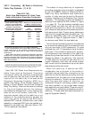
to insure the longevity of the product. Ambient
temperature is also a design consideration when
FRP cable tray is used. An ambient temperature of
100°F will decrease the loading capacity of poltester
resin fiberglass cable tray by 10%.
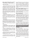
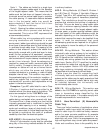
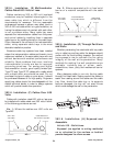
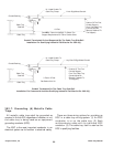
392.6. Installation. (A) Complete System.
This section states that cable tray systems can
have mechanically discontinuous segments, and that
the mechanically discontinuous segment cannot be
greater than 6 feet. A bonding jumper sized per
Section 250.102 is necessary to connect across any
discontinuous segment. The bonding of the system
should be in compliance with Section 250.96.
21
Cable Tray Manual Cooper B-Line, Inc
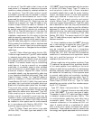
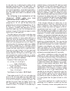
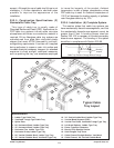
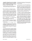
Nomenclature
1. Ladder Type Cable Tray 10. 30° Vertical Inside Bend, Ladder Type Tray
2. Ventilated Trough Type Cable Tray 11. Vertical Bend Segment (VBS)
3. Splice Plate 12. Vertical Tee Down, Ventilated Trough Type Tray
4. 90° Horizontal Bend, Ladder Type Tray 13. Left Hand Reducer, Ladder Type Tray
5. 45° Horizontal Bend, Ladder Type Tray 14. Frame Type Box Connector
6. Horizontal Tee, Ladder Type Tray 15. Barrier Strip Straight Section
7. Horizontal Cross, Ladder Type Tray 16. Solid Flanged Tray Cover
8. 90° Vertical Outside Bend, Ladder Type Tray 17. Cable Channel Straight Section, Ventilated
9. 45° Vertical Outside Bend, Ventilated Type Tray 18. Cable Channel, 90° Vertical Outside Bend
1
2
3
4
6
7
8
10
11
12
13
14
15
16
17
18
Typical Cable
Tray Layout
5
9
Cable Tray Elevation Change Without Fittings
Bonding
Jumper