


problems due to operating standard three conductor
cables with standard sized EGCs in parallel. This has
been a standard industrial practice for over 40 years
with large numbers of such installations in service.
This change was made without any safety or
technical facts to justify this change.
To comply with Section 250.122, Three options
are available: 1. Order special cables with increased
sized EGCs which increases the cost and the
delivery time. 2. Use three conductor cables without
EGCs and install a single conductor EGC in the
cable tray or use the cable tray as the EGC in
qualifying installations. 3. Use standard cables but
don’t utilize their EGCs, use a single conductor EGC
or the cable tray as the EGC in qualifying
installations.
Should industry be required to have special cables
fabricated for such installations when there have
been absolutely no safety problems for over 40
years? Each designer and engineer must make his
own decision on this subject. If the installations are
properly designed, quality materials are used, and
quality workmanship is obtained, there is no safety
reason for not following the past proven practice of
paralleling the EGCs of standard three conductor
cable.
392.8. Cable Installation. (E) Single
Conductors.
This section states that single conductors in ladder
or ventilated trough cable tray that are Nos. 1/0
through 4/0, must be installed in a single layer.
In addition to the fill information that is in Section
392.10(A)(4), an exception was added which allows
the cables in a circuit group to be bound together
rather than have the cables installed in a flat layer.
The installation practice in the exception is desirable
to help balance the reactance’s in the circuit group.
This reduces the magnitudes of voltage unbalance in
three phase circuits.
Where ladder or ventilated trough cable trays
contain multiconductor power or lighting cables, or
any mixture of multiconductor power, lighting,
control, or signal cables, the maximum number of
cables that can be installed in a cable tray are limited
to the Table 392.9 allowable fill areas. The cable
tray fill areas are related to the cable ampacities.
Overfill of the cable tray with the conductors
operating at their maximum ampacities will result in
cable heat dissipation problems with the possibility
of conductor insulation and jacket damage.
392.9. Number of Multiconductor Cables.
Rated 2000 Volts or less, in Cable Trays.
(A) Any Mixture of Cables. (1) 4/0 or
Larger Cables
The ladder or ventilated trough cable tray must
have an inside usable width equal to or greater than
the sum of the diameters (Sd) of the cables to be
installed in it. For an example of the procedure to
use in selecting a cable tray width for the type of
cable covered in this section
see page 47 (Appendix
Sheet 3), [Example 392.9(A)(1)].
Increasing the cable tray side rail depth increases
the strength of the cable tray but the greater side rail
depth does not permit an increase in cable fill area
for power or lighting cables or combinations of
power, lighting, control and signal cables. The
maximum allowable fill area for all cable tray with a
3 inch or greater loading depth side rail is limited to
the 38.9 percent fill area for a 3 inch loading depth
32
Cooper B-Line, Inc Cable Tray Manual
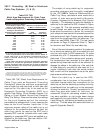
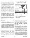
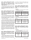
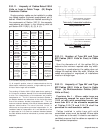
Compatibility Of Cable Tray Types And
Cable Trays Based On The NEC
®
3", 4", & 6" Wide Solid or
Ventilated Channel Cable Tray
Solid Bottom Cable Tray
Ventilated Trough Cable Tray
Ladder Cable Tray
X - Indicates the Installations Allowed by Article 392
* - For cables rated up to 2000 volts.
** - For cables rated above 2000 volts.
*** - For 1/0 - 4/0 AWG single conductor cables
installed in ladder cable tray, maximum rung
spacing is 9 inches.
X X X X
* * *
X X
X
X X X
X X X
Multiconductor Cables
300 & 600 Volt *
Single Conductor
Cables - 600 Volt *
Type MV Multiconductor
Cables **
Type MV Single Conductor
Cables **