


moisture content, however the minimum density
that should be used for snow is 5 pounds per cubic
foot. The engineer will have to contact the weather
service to determine the potential snow falls for the
installation area or consult the local building code
for a recommended design load.
Usually cable trays are installed within structures
such that the structure and equipment shelter the
cable trays from the direct impact of high winds. If
wind loading is a potential problem, a structural
engineer and/or the potential cable tray
manufacturer should review the installation for
adequacy. To determine the wind speed for proper
design consult the Basic Wind Speed Map of the
United States in the NESC
(Figure 250-2).
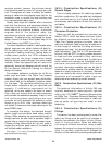
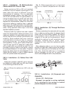
For those installations located in earthquake areas,
design engineers can obtain behavioral data for
B-Line cable trays under horizontal, vertical and
longitudinal loading conditions. Testing done for
nuclear power plants in the 1970's indicates that
cable trays act like large trusses when loaded
laterally and are actually stronger than when loaded
vertically. Cable tray supports may still need to be
seismically braced and designers should consult the
B-Line Seismic Restraints Catalog for detailed
design information.
The midspan deflection multipliers for all B-Line
cable trays are listed in the Cable Tray Systems
catalog. Simply pick your support span and multiply
your actual load by the deflection multiplier shown
for that span. The calculated deflections are for
simple beam installations at your specified load
capacity. If a deflection requirement will be
specified, extra care needs to be taken to ensure
that it does not conflict with the load requirement
and provides the aesthetics necessary. Keep in mind
that continuous beam applications are more
common and will decrease the deflection values
shown by up to 50%. Also, aluminum cable trays
will deflect 3 times more than steel cable trays of the
same NEMA class.
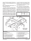
To complete the design, the standard straight
section length and minimum bend radius must be
chosen. When selecting the recommended length of
straight sections, be sure that the standard length is
greater than or equal to the maximum support span.
Choose a fitting radius which will not only meet or
exceed the minimum bend radius of the cables but
will facilitate cable installation.
[See page 11 for more information on selecting the
appropriate cable tray length]
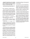
392.5. Construction Specifications. (B)
Smooth Edges.
This is a quality statement for cable tray systems
and their construction. B-Line cable tray is designed
and manufactured to the highest standards to
provide easy, safe installation of both the cable tray
and cables.
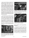
392.5. Construction Specifications. (C)
Corrosion Protection.
Cable tray shall be protected from corrosion per
Section 300.6, which lists some minimum criteria
for different corrosive environments. The B-Line
Cable Tray Catalog contains a corrosion chart for
cable tray materials. Cable trays may be obtained in
a wide range of materials including aluminum,
pregalvanized steel, hot dipped galvanized steel
(after fabrication), Type 304 or 316 stainless steel,
polyvinyl chloride (PVC) or epoxy coated aluminum
or steel and also nonmetallic (fiber reinforced
plastic). Check with a metallurgist to determine
which metals and coatings are compatible with a
particular corrosive environment. B-Line has
corrosion information available and may be able to
recommend a suitable material. Remember that no
material is totally impervious to corrosion. Stainless
steel can deteriorate when attacked by certain
chemicals and nonmetallic cable trays can
deteriorate when attacked by certain solvents.
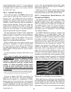
392.5. Construction Specifications. (D) Side
Rails.
The technical information in Article 392 was
originally developed for cable trays with rigid side
rails by the 1973 NEC
®
Technical Subcommittee
on Cable Tray. “Equivalent Structural Members” was
added later to incorporate new styles of cable tray
such as center rail type tray and ‘mesh’ or wire
basket tray.
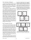
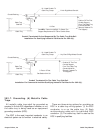
392.5. Construction Specifications. (E)
Fittings.
This section has been misinterpreted to mean that
cable tray fittings must be used for all changes in
direction and elevation [See Section 392.6(A) Complete
system for further explanation)
. When two cable tray
runs cross at different elevations, lacing a cable
between the rungs of one tray and dropping into the
other is a common practice which changes the
direction of the cable while providing adequate cable
20
Cooper B-Line, Inc Cable Tray Manual