


48
Cooper B-Line, Inc Cable Tray Manual
Appendix Sheet 4
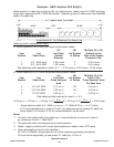
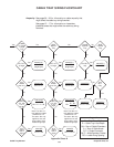
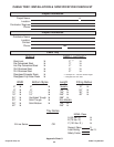
Example - NEC
®
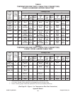
Section 392.9(A)(2)
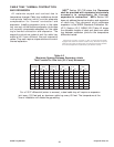
Width selection for cable tray containing 600 volt multiconductor cables, sizes #3/0 AWG and
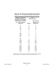
smaller. Cable tray allowable fill areas are listed in Column 1 of Table 392.9.
Cable tray width is obtained as follows:
(A) (N) Multiply (A) x (N)
Item List List Cable List Total of the
Number Cable Sizes Cross Sectional Number Cross Sectional
Areas of Cables Area for Each Item
1. 3/C #12 AWG 0.17 sq. in. 20 3.40 sq. in.
2. 4/C #12 AWG 0.19 sq. in. 16 3.04 sq. in.
3. 3/C #6 AWG 0.43 sq. in. 14 6.02 sq. in.
4. 3/C #2 AWG 0.80 sq. in. 20 16.00 sq. in.
Method 1.
The sum of the total areas for items 1, 2, 3, & 4:
3.40 sq. in. + 3.04 sq. in. + 6.02 sq. in. + 16.00 sq. in. = 28.46 sq. inches
From Table 392.9 Column 1 a 30 inch wide tray with an allowable fill area of 35 sq. in.
must be used. The 30 inch cable tray has the capacity for additional future cables (6.54
sq. in. additional allowable fill area can be used.)
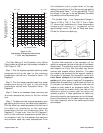
Method 2.
The sum of the total areas for items 1, 2, 3, & 4 multiplied by
3.40 sq. in. + 3.04 sq. in. + 6.02 sq. in. + 16.00 sq. in. = 28 46 sq. in.
Use a 30 inch wide cable tray.
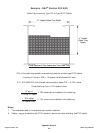
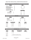
Notes:
1. The cable sizes used in this example are a random selection.
2. Cables - copper conductors with cross linked polyethylene insulation and a PVC jacket.
(These cables could be ordered with or without an equipment grounding conductor.)
3. Total cable weight per foot for this installation.
31.9 lbs./ft. (Cables in this example do not contain equipment grounding conductors.)
This load can be supported by a load symbol "A" cable tray - 50 lbs./ft.
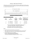
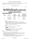
30" Usable Cable Tray Width
Cross Section Of The Cables And The Cable Tray
( )
6 in.
7 sq. in.
= cable tray width required
( )
28.46 sq. in. x 6 in.
7 sq. in.
= 24.39 inch cable tray width required