


42
Cooper B-Line, Inc Cable Tray Manual
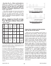
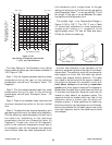
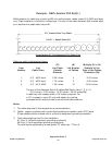
The Gap Setting of the Expansion Joint Splice
Plate is used as follows per the example indicated in
VE-2 Figure 4.13B.
Step 1. Plot the highest expected cable tray metal
temperature during the year on the maximum
temperature vertical axis. Example's Value: 100
Degrees F.
Step 2. Plot the lowest expected cable tray metal
temperature during the year on the minimum
temperature vertical axes. Example's Value: - 28
Degrees F.
Step 3. Draw a line between these maximum and
minimum temperature points on the two vertical
axis.
Step 4. To determine the required expansion joint
gap setting at the time of the cable tray's installation:
Plot the cable tray metal temperature at the time of
the cable tray installation on the maximum
temperature vertical axis (Example's Value: 50
Degrees F). Project over from the 50 Degrees F
point on the maximum temperature vertical axis to
an intersection with the line between the maximum
and minimum cable tray metal temperatures. From
this intersection point, project down to the gap
setting horizontal axis to find the correct gap setting
value (Example's Value:
3
/8 inch gap setting). This is
the length of the gap to be set between the cable
tray sections at the expansion joint.
The plotted High - Low Temperature Range in
Figure 4-13B is 128° F. The 125° F line in Table
4-1 shows that installations in these temperature
ranges would require
3
/8” expansion joints
approximately every 102 feet for Steel and every
52 feet for Aluminum cable tray.
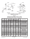
Another item essential to the operation of the
cable tray expansion splices is the type of hold down
clamps used. The cable tray must not be clamped to
each support so firmly that the cable tray cannot
contract and expand without distortion. The cable
tray needs to be anchored at the support closest to
the midpoint between the expansion joints with
hold down clamps and secured by expansion
guides at all other support locations.The expansion
guides allow the cable tray to slide back and forth as
it contracts and expands. Supports must also be
located on both sides of an expansion splice. The
supports should be located within two feet of the
expansion splice to ensure that the splice will
operate properly. If these guidelines for cable tray
thermal contraction and expansion are not followed,
there is the potential for the cable trays to tear loose
from their supports, and for the cable trays to bend
and collapse.
Max. Temp. Min. Temp.
Figure 4.13B
Gap Setting Of Expansion Splice Plate
1" (25.4 mm) Gap Maximum
130
110
90
70
50
30
10
-10
-30
50
C° F° F°
40
30
20
10
0
-10
-20
-30
-40
130
110
90
70
50
30
10
-10
-30
0
1
/8
5
/8
1
/2
3
/8
1
/4
1
7
/8
3
/4
Gap Setting in Inches
Metal Temperature At Time
Of Installation (F° or C°)
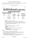
As a clamp.
As a guide.
1
2
3
4