


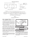
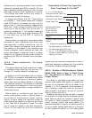
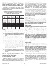
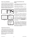

392.10. Number of Single Conductor
Cables, Rated 2000 Volts or Less in Cable
Trays. (B) Ventilated Channel Cable Trays.
The sum of the diameters (Sd) of all single
conductors shall not exceed the inside width of the
ventilated cable channel.
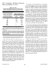
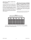
Number Of 600 Volt Single Conductor Cables
That May Be Installed In A Ventilated Channel
Cable Tray - Section 392.10(B)
392.11. Ampacity of Cables Rated 2000
Volts or Less in Cable Trays.
(A) Multiconductor Cables.
Ampacity Tables 310.16 and 310.18 are to be
used for multiconductor cables which are installed in
cable tray using the allowable fill areas as per Section
392.9. The ampacities in Table 310.16 are based
on an ambient temperature of 30˚ Celsius. Conduit
and cable tray wiring systems are often installed in
areas where they will be exposed to high ambient
temperatures. For such installations, some designers
and engineers neglect using the Ampacity Correction
Factors listed below the Wire Ampacity Tables which
results in the conductor insulation being operated in
excess of its maximum safe temperature. These
correction factors must be used to derate a cable for
the maximum temperature it will be subjected to
anywhere along its length.
392.11(A)(1)
Section 310.15(B)(2)(a) refers to Section 392.11
which states that the derating information of Table
310.15(B)(2)(a) applies to multiconductor cables with
more than three current carrying conductors but not
to the number of conductors in the cable tray.
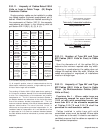
392.11(A)(2)
Where cable trays are continuously covered for more
than 6 feet (1.83m) with solid unventilated covers,
not over 95 percent of the allowable ampacities of
Tables 310.16 and 310.18 shall be permitted for
multiconductor cables.
This is for multiconductor cables installed using
Table 392.16 or 392.18. If these cables are installed
in cable trays with solid unventilated covers for more
than 6 feet the cables must be derated. Where cable
tray covers are to be used, it is best to use raised or
ventilated covers so that the cables can operate in a
lower ambient temperature.
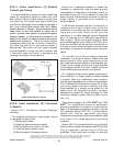
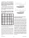
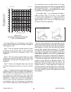
392.11(A)(3)
Where multiconductor cables are installed in a
single layer in uncovered trays, with a maintained
spacing of not less than one cable diameter between
cables, the ampacity shall not exceed the allowable
ambient temperature corrected ampacities of
multiconductor cables, with not more than three
insulated conductors rated 0-2000 volts in free air, in
accordance with Section 310.15(C).
By spacing the cables one diameter apart, the
engineer may increase the allowable ampacities of
the cables to the free air rating as per Section
310.15(C) and Table B-310.3 in Appendix B.
Notice that the allowable fill of the cable tray has
been decreased in this design due to the cable
spacing.
36
Cooper B-Line, Inc Cable Tray Manual
Notes:
#1. Cable diameter's used are those for Okonite-
Okolon 600 volt single conductor power cables.
#2. Such installations are to be made only in qualifying
industrial facilities as per Sections 392.3(B) &
(B)(1).
#3. The phase, neutral, and EGCs cables are all
counted in the allowable cable fill for the ventilated
channel cable tray.
#4. To avoid problems with unbalanced voltages, the
cables should be bundled with ties every three feet
or four feet. The bundle must contain the circuit's
three phase conductors plus the neutral if one is
used. If a cable is used as the EGC, it should also
be in the cable bundle. If the designer desires, the
ventilated channel cable tray may be used as the
EGC as per Table 392.7(B)(2).
#5. The single conductor cables should be firmly tied to
the ventilated channel cable tray at six foot or less
intervals.
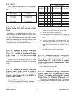
Single Diameter 3 Inch 4 Inch 6 Inch
Conductor Inches V. Channel V. Channel V. Channel
Size (Note #1) C.T. C.T. C.T.
1/0 AWG 0.58 5 6 10
2/0 AWG 0.62 4 6 9
3/0 AWG 0.68 4 5 8
4/0 AWG 0.73 4 5 8
250 Kcmil 0.84 3 4 7
350 Kcmil 0.94 3 4 6
500 Kcmil 1.07 2 3 5
750 Kcmil 1.28 2 3 4
1000 Kcmil 1.45 2 2 4