


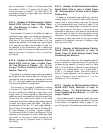
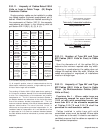


392.11. Ampacity of Cables Rated 2000
Volts or Less in Cable Trays. (B) Single
Conductor Cables.
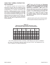
Single conductor cables can be installed in a cable
tray cabled together (triplexed, quadruplexed, etc.) if
desired. Where the cables are installed according to
the requirements of Section 392.10, the ampacity
requirements are shown in the following chart as
per Section 392.11(B)(1), (2), (3), & (4):
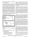
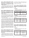
392.12. Number of Type MV and Type
MC Cables (2001 Volts or Over) in Cable
Trays.
Sum the diameters of all the cables (Sd) to
determine the minimum required cable tray width.
Triplexing or quadruplexing the cables does not
change the required cable tray width. Whether the
cables are grouped or ungrouped, all installations
must be in a single layer.
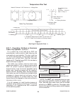
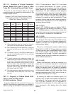
392.13. Ampacity of Type MV and Type
MC Cables (2001 Volts or Over) in Cable
Trays. (A) Multiconductor Cables (2001
Volts or Over).
Provision No. 1: Where cable trays are
continuously covered for more than six feet
(1.83 m) with solid unventilated covers, not
more than 95% of the allowable ampacities
of Tables 310.75 and 310.76 shall be
permitted for multiconductor cables.
Cables installed in cable trays with solid
unventilated covers must be derated. Where cable
tray covers are to be used, it is best to use raised or
ventilated covers so that the cables can operate in a
lower ambient temperature.
37
Cable Tray Manual Cooper B-Line, Inc
Mult.
Solid Applicable Amp.
Sec. Cable Unventilated Ampacity Table Special
No. Sizes Cable Tray Tables Values Conditions
Cover (*) By
600 kcmil No Cover 310.17
(1) and Allowed and 0.75
Larger (**) 310.19
600 kcmil 310.17
(1) and Yes and 0.70
Larger 310.19
1/0 AWG No Cover 310.17
(2) through Allowed and 0.65
500 kcmil (**) 310.19
1/0 AWG 310.17
(2) through Yes and 0.60
500 kcmil 310.19
1/0 AWG Maintained
(3) & Larger No Cover 310.17 1.00 Spacing Of
In Single Allowed and One Cable
Layer (**) 310.19 Diameter
Single
Conductors 310.20 Spacing Of
(4) In Triangle No Cover [See NEC 2.15 x One
Config. Allowed Section 1.00 Conductor
1/0 AWG (**) 310.15(B)] O.D.
Between
and Larger Cables(***)
(*) The ambient ampacity correction factors must be used.
(**) At a specific position, where it is determined that the tray
cables require mechanical protection, a single cable tray cover of
six feet or less in length can be installed.
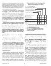
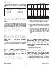
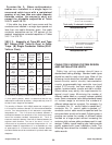
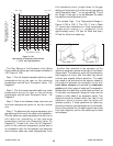
The wording of Section 392.11(B)(4) states that a spacing of
2.15 times one conductor diameter is to be maintained between
circuits. Two interpretations of this statement are possible.
Interpretation #1. - The 2.15 times one conductor diameter is
the distance between the centerlines of the circuits (the center
lines of the conductor bundles). Interpretation #2. - The 2.15
times one conductor diameter is the free air distance between the
adjacent cable bundles. The use of the word “circuit” is
unfortunate as its presence promotes Interpretation #1. An
installation based on Interpretation #1 is not desirable as a free
air space equal to 2.15 times one conductor diameter between
the cable bundles should be maintained to promote cable heat
dissipation.
Spacing Between Conductors
(2.15 x O.D. of Conductor)
Technically Desirable Installation
Spacing Between Conductors
(2.15 x O.D. of Conductor)
Technically Undesirable Installation
Interpretation #1
Interpretation #2