


Setup
312759R 49
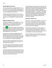
External Control Interface Setup
The external control interface allows an external
machine to control the PR70. The external machine can
use Connector #1 to send dispense request and abort
commands. Also, Connector #1 indicates to the external
machine whether the PR70 is ready to dispense.
Connector #2 is used to select a shot number. See F
IG.
33 for connector location on the PR70.
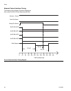
Ready-Output Status Line
The Ready-Output status line (“READY-OUTPUT” in
F
IG. 32, Connector #1, Pin #2) is a signal provided to the
external control. The line indicates whether a shot or
dispense request will be accepted by the machine. The
output of the Ready-Output status line is a “high”
+24 VDC signal when the system is ready to dispense.
The output is a “low” +15 VDC signal when the system
is not ready to dispense. See F
IG. 34 on page 52 for a
sample timing diagram.
The following conditions will make the machine not
ready to accept a dispense request.
• Dispensing in progress.
• User is programming the display module.
• Active error code that has not been acknowledged.
• Auto-Sequencing in progress.
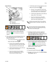
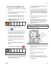
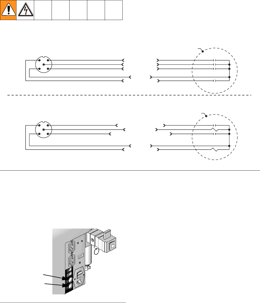
FIG. 32: External Control Interface Electrical Diagram
Connector #2
Connector #1
4
5
1
3
2
4
5
1
3
2
Customer Supplied
Dry Contact/Relay
Customer Supplied
Dry Contact/Relay
SHOT SEL - BIT 0
SHOT SEL - BIT 3
SHOT SEL - BIT 2
COMMON
SHOT SEL - BIT 1
SHOT REQUEST - INPUT
FAULT OUTPUT
INTERRUPT - CAN - REQ - INPUT
COMMON
READY - OUTPUT
Brown
Gray
Black
Blue
White
Brown
+24 VDC
+24 VDC
Gray
Black
Blue
White
NOTE: Connector #1 is for use with all systems.
NOTE: View shown is looking at pins on end of cable.
NOTE: Connector #2 is for use with systems with an Advanced
Display Module only.
NOTE: View shown is looking at pins on end of cable.
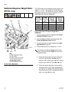
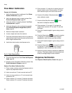
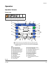
FIG. 33: External Control Connectors
Connector #1
Connector #2
ti12583a