


-22-
Model G0747/G0748 (Mfg. Since 8/12)
Assembly
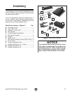
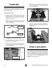
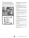
Figure 10. Ball handle assemblies.
Ball Handle
Handle
Ball Handle
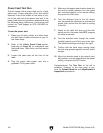
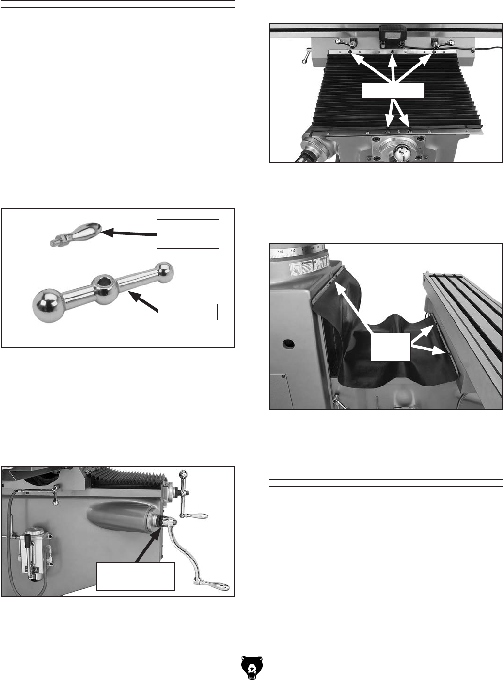
4. Using the five cap screws pre-threaded into
the holes, install the front way cover as
shown in Figure 12.
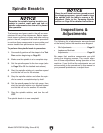
5. Using the four cap screws pre-threaded into
the holes, install the rear way cover as shown
in Figure 13.
Initial Lubrication
The machine was fully lubricated at the factory,
but we strongly recommend that before perform-
ing the Test Run you inspect all lubrication
points yourself and provide additional lubrication
if necessary. Refer to the Lubrication section on
Page 44 for specific details.
Assembly of the small components of the mill
consists of attaching the ball handles, knee crank,
and the way covers.
To assemble the mill:
1. Remove the hex nuts from the X- and
Y-axis leadscrews, then slide the ball handles
(Figure 10) onto the leadscrews and secure
them with the hex nuts.
Note: Tighten the hex nuts just until they are
snug. Overtightening could increase the wear
of the moving parts.
2. Thread the handles into the small end of the
ball handles and tighten them.
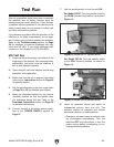
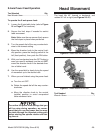
3. Slide the knee crank onto the shaft so that
the teeth of the crank and shaft engage, as
shown in Figure 11.
Figure 11. Knee crank teeth engaged.
Knee Crank
Teeth Engaged
Figure 12. Front way cover installed.
Cap Screws
Figure 13. Rear way cover installed.
Cap
Screws