


Model G0747/G0748 (Mfg. Since 8/12)
-27-
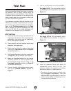
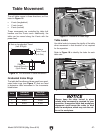
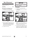
Table Movement
The mill table moves in three directions, as illus-
trated in Figure 16:
• X-axis (longitudinal)
• Y-axis (cross)
• Z-axis (vertical)
These movements are controlled by table ball
handles and the Z-axis crank. Additionally, the
table can be moved along the X-axis with the
power feed.
X-Axis or Longitudinal Travel
(Left & Right)
Y-Axis or
Cross Travel
(In & Out)
Z-Axis or
Vertical Elevation
(Up & Down)
Figure 16. The directions of table movement.
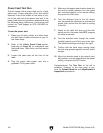
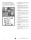
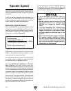
Graduated Index Rings
The table ball handles and knee crank have grad-
uated index rings (see Figure 17) that are used
to determine table movement in the increments
listed below:
Axis
Individual
Increment
One Full
Revolution
X 0.001" 0.200"
Y 0.001" 0.200"
Z 0.001" 0.100"
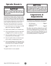
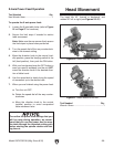
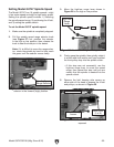
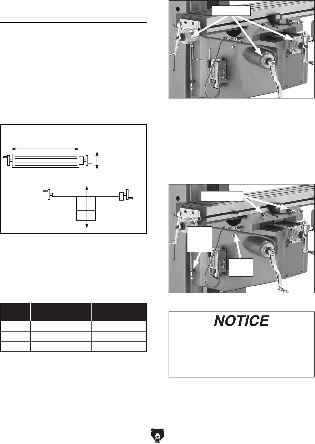
Table Locks
Use table locks to increase the rigidity of the table
when movement in that direction is not required
for the operation.
Refer to Figure 18 to identify the locks for each
table axis.
Figure 18. Locations of table locks for each axis.
Z-Axis
Lock
(1 of 2)
Y-Axis
Lock
X-Axis Locks
Figure 17. Locations of index rings.
Index Rings
Always keep the table locked in place
unless table movement is required for your
operation. Unexpected table and workpiece
movement could cause the cutter to bind
with the workpiece, which may ruin the cut-
ter or the workpiece.