


Masterpage:Left-FullCol
8 EN
Filename [HM-100U_Eng_05Index.fm]
INDEX (cont.)
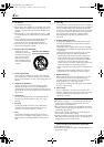
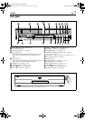
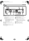
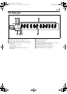
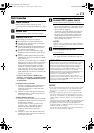
Rear panel
A AC power cord : A page 13
B Cooling fan
•This prevents the temperature from rising inside the
VCR. Do not remove it.
•Install the VCR so as not to block the area around
the cooling fan.
•The cooling fan may be activated even if the unit is
turned off in the following case;
— if the Auto Clock Set and Auto Tuner Set have
not been completed automatically by the Plug &
Play setting. (A page 14)
Setting the clock manually (A page 17) will
turn off the cooling fan.
C [COMPONENT VIDEO OUT] connectors :
A page 13
D [S VIDEO]/[AUDIO]/[VIDEO OUTPUT] connectors :
A page 13
E [S VIDEO]/[AUDIO]/[VIDEO INPUT] connectors
(L-1) : A page 82
F [S VIDEO]/[AUDIO]/[VIDEO INPUT] connectors
(L-2) : A page 82
G [REMOTE PAUSE/AV COMPULINK] terminal
•[REMOTE PAUSE] terminal : A page 83
•[AV COMPULINK] terminal : A page 69
H [CABLE BOX] Controller connector : A page 22, 25
I [JLIP] terminal : A page 77
J [ANTENNA OUT] terminal : A page 13
K [i.LINK IN/OUT], [DV IN] Connector (i.Link*) :
A page 80
* i.Link refers to the IEEE1394-1995 industry
specification and extensions thereof. The A logo is
used for products compliant with the i.Link
standard.
L [HDMI OUT] connector: A page 13
M [OPTICAL] terminal : A page 13, 66
N [ATSC IN] terminal : A page 13
O [ANTENNA IN] terminal : A page 13
REMOTE PAUSE/
AV COMPULINK
CABLE BOX
ATSC IN
VHF/UHF
IN
ANTENNA
ANTENNA
L-2
PCM/STREAM
DIGITAL AUDIO OUT
OPTICAL
PB/CB
PR/CR
Y
COMPONENT
VIDEO OUT
OUTPUT
HDMI OUT
D-THEATER
REGION 1
i.LINK IN/OUT
DV IN
L-1
S400
INPUT
S-VIDEO
VIDEO
L
AUDIO
R
S-VIDEO
VIDEO
L
AUDIO
R
OUT
A
B
C D E F G H J
ONK L M
I
HM-DH100U_Eng.book Page 8 Thursday, August 5, 2004 1:54 PM