


The RC Configuration Software
13
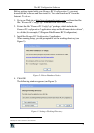
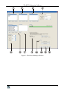
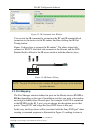
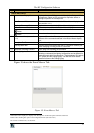
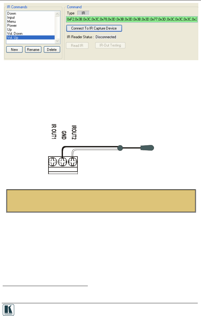
Figure 13: IR Command Area Window
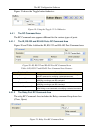
You can test the IR command by connecting the RC unit IR terminal block
connectors to the device via the IR emitter, and then clicking the IR-Out
Testing button.
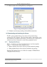
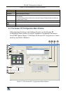
Figure 14 shows how to connect the IR emitter
1
. The white striped side
connects to IR OUT, the black side connects to the Ground, and the LED
Emitter Shell is affixed to the IR sensor window with the adhesive layer.
Figure 14: IR Emitter Wiring
NOTE: The dual IR emitter emits a weaker IR signal that may not be detected
by some devices
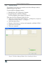
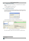
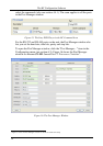
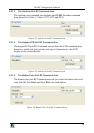
4.3 Port Mapping
The Port Manager window defines the ports on the Master device (SV-551 or
RC-6x, depending on the type of installation) and lets you write a description
and assign a default driver for each port. For example, if a DVD is connected
to the SV-551 via the IR_2 port, you can change the description next to that
port to “Sony DVD” and assign the Sony DVD driver to this port.
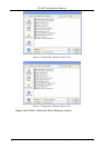
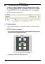
In this way, the Sony driver will be associated with the Sony DVD port
2
when
creating a command sequence as illustrated in Figure 15, making it easier to
1 Using the Kramer 3.5mm to IR Emitter Control Cable (C-A35/IRE-10)
2 Although you can assign it with a different Vendor or Device