


INSTALLATION
19
Connections (Continued)
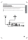
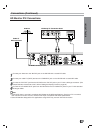
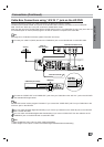
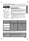
Cable Box Connections using “A/V IN 1” jack on the HD DVR
Use your HD DVR to control your cable box with the TV Guide On Screen™ system.
Locate the jack marked G-LINK. This jack is for the G-LINK cable. Insert the connector into the G-LINK jack.
Note: If there is a “demo pin” in the jack, remove it to disable demo mode.
Place the other end of the G-LINK cable with the G-LINK wand in front of your Cable Box in such a way as to allow for
an unrestricted path for the IR (infrared) signal to be able to reach the front panel of the Cable Box.
ote
See page 54 for TV Guide On Screen system information and set up.
1
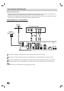
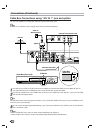
Connect your cable TV (CATV) service to the “CABLE IN” jack on the HD DVR with a coaxial RF cable.
2
Connect the “AUDIO OUT” and “VIDEO OUT” jacks from your Cable Box to the “A/V IN 1” jack on the HD DVR
with standard RCA-type cables.
ote
The HD DVR cannot receive program information if you connect the “VIDEO OUT” jack from your Cable Box to the
“A/V IN 2” jack on the HD DVR.
3
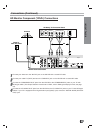
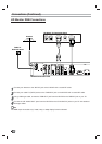
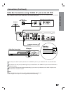
You can watch terrestrial digital broadcasting if you connect your Antenna to the “ANT IN” jack on the HD DVR
with a coaxial RF cable.
4
You can watch unscrambled digital cable broadcasting if you connect “LOOP OUT” from the cable box to the
“CABLE IN” jack on the HD DVR with a coaxial RF cable.
otes
• Select “Cable Box” menu option to watch cable broadcasting.
• Select “Digital” menu option to watch unscrambled digital terrestrial/cable broadcasting.
L
R
AUDIO OUTPUT
VIDEO
OUTPUT
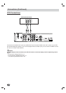
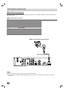
HD DVR Connection Panel
Cable Box Connection Panel
Cable Box (front view)
Cable Box
(side view)
1/2" to 1"
IR Sensor
Cable Box Controller
Cable TV
Wall Jack Panel
Antenna
CABLE
INPUT
LOOP OUT