


29
Chapter 2. Connecting
See Appendix B for component video signal
compatibility information.
For digital audio connections to your A/V
receiver , see your HDTV Receiver and A/V
receiver Owner’s Guides.
IMPORTANT
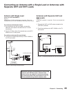
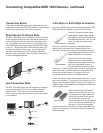
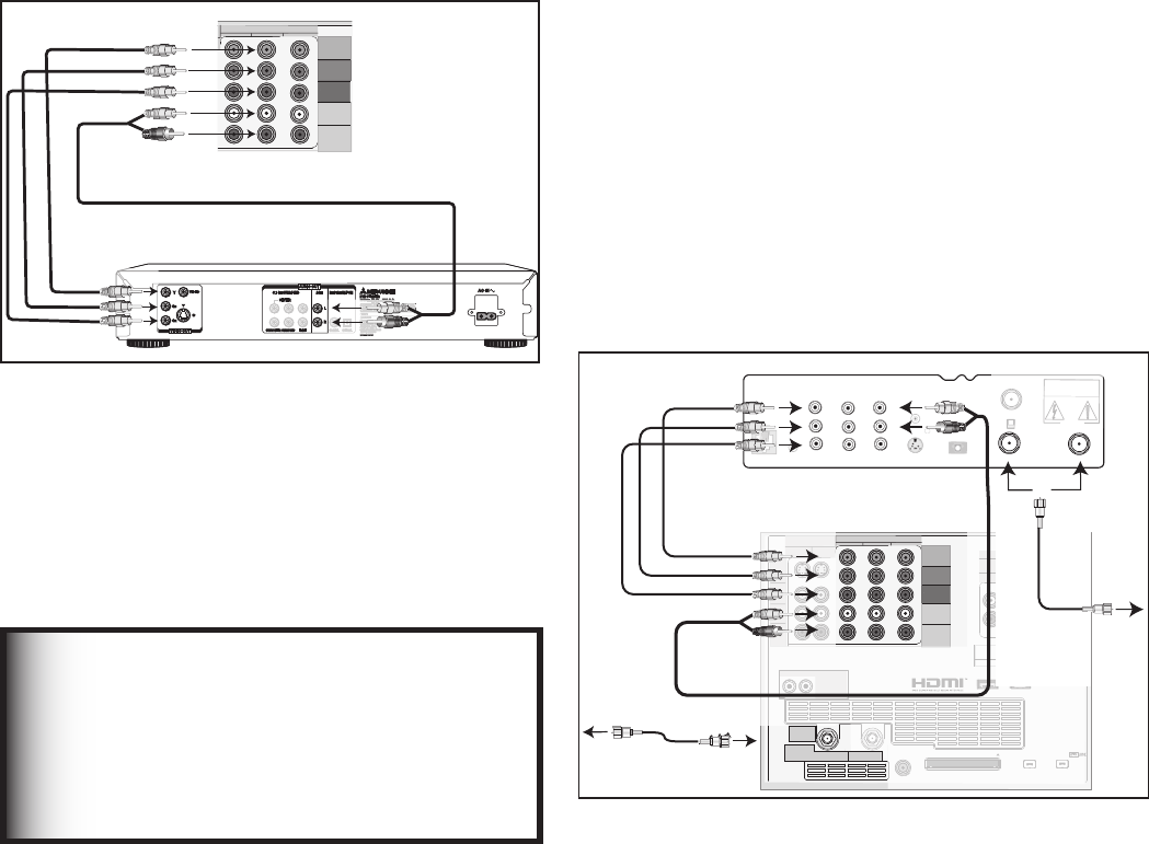
Connecting a DVD Player with Component Video
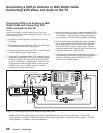
Connecting an HDTV Cable Box or Satellite Receiver with
Component Video
DVD Player with Component Video
Figure 9
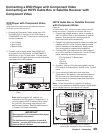
Component video cables and audio cables are required.
These are not included with the TV.
1. Connect the Component Video cables from Y/Pr/
Pb VIDEO OUT on the back of the DVD player to
COMPONENT-2 on the TV back panel, matching the
correct connection:
• Y to Y (Green)
• Pr to Pr (Red)
• Pb to Pb (Blue)
2. Connect a set of audio cables from AUDIO OUT
on the back of the DVD player to COMPONENT-2
AUDIO Input on the TV back panel. The red cable
connects to the R (right) channel, and the white cable
connects to the L (left) channel.
COMPONENT
YPbPr (480i/480p/720p/1080i)
1
2
Y
Pb
Pr
AUDIO-
LEFT/
(MONO)
AUDIO-
RIGHT
3
7*%&0
4
:
$#
$3
7*%&0065
#*5453&".1$.$)463306/% $)
-
3
$&/5&3
46#800'&3463306/% '30/5 $0"9*"- 015*$"-
"6%*0065
"$*/
.*546#*4)*
%7%1-":&3
.0%&-
%%
108&34611-:7_)[
108&3$0/46.15*0/8
.*546#*4)*%*(*5"-&-&$530/*$4
%*453*#65&%#:
+&30/*.030"%
*37*/&$"
."%&*/+"1"/
".&3*$"*/$
4&3*"-/0
."/6'"$563&%
3FE
%7%CBDLQBOFM
57CBDLQBOFMTFDUJPO
8IJUF
3FE
3FE
8IJUF
5P57$PNQPOFOU
:131CJOQVUT
Note: NetCommand® will assume you
connected your DVD player to Component-2. If
you add a second DVD or use any other inputs
for your DVD, this change must match in the
NetCommand system. See Edit NetCommand...
in Chapter 3 for more information.
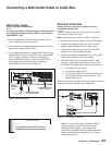
Figure 9. Connecting a DVD Player with Component
Video
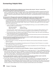
HDTV Cable Box or Satellite Receiver
with Component Video
Figure 10
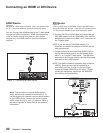
A coaxial splitter, RCA component video cables, and audio
cables are required. These are not included with the TV.
1. Connect the outside antenna, cable, or satellite to
ANT or SATELLITE IN on the cable box or satellite
receiver. See your device’s owner’s guide for
instructions and cable compatibility.
2. Connect the incoming terrestrial antenna or cable (not
satellite) to ANT-1 on the TV back panel (a coaxial
splitter, available at most electronic supply stores,
may be required to complete this installation).
3. Connect RCA-type cables from the YPrPb outputs
on the DTV receiver to Component-1 on the TV back
panel, matching the correct connections:
DTV Receiver to TV Back panel
• Y to Y
• Pr to Pr
• Pb to Pb
4. Connect L (left) and R (right) audio cables from the
DTV receiver to Component-1 AUDIO on the TV back
panel.
5. If you are using a cable-box input other than
Component-1 (the default), open the NetCommand
RF Connection for Cable screen (see page 49) or
the Connection for [device] screen (see page 48) to
change the input.
Note: To use the benefits of a digital A/V receiver,
connect your cable box or satellite receiver’s digital audio
out to a digital input on your digital A/V receiver.
%573FDFJWFSXJUI:1S1CDPOOFDUJPOT
7*%&0
:
1S
1C
47*%&0
7$3
$0/530-
1)0/&+"$,
3'
3&.05&
0655057
$)
$)
$"65*0/
3*4,0'&-&$53*$"-4)0$,
%0/0501&/
%*(*5"-
"6%*0065
8IJUF
3FE
4"5&--*5&*/
*/'30."/5
PS
"6%*0
-
3
"6%*0
-
3
7*%&0
57CBDLQBOFMTFDUJPO
COMPONENT
YPbPr (480i/480p/720p/1080i)
INPUT
1
2
S-VIDEO
VIDEO
AUDIO-
LEFT/
(MONO)
AUDIO-
RIGHT
ANT 2 / AUX
DIGITAL
AUDIO
OUTPUT
CableCARD™ USE WITH ANT 1 CARD TOP
1
2
Y
Pb
Pr
AUDIO-
LEFT/
(MONO)
AUDIO-
RIGHT
OUTPUT
AUDIO
OUTPUT
RECORD
OUTPUT
DVI
Analog Audio
1 2
VIDEO
AUDIO-
LEFT/
(MONO)
AUDIO-
RIGHT
SERVICE
PORT
MONITORLINK™/HDMI
VIDEO 480i/480p/720p/1080i
AUDIO PCM LINEAR
1
2
IEEE 1394
INPUT/
OUTPUT
Net Command
IR EMITTER
¸
',INK
¸
INPUT
3
*ODPNJOH"OUFOOB
PS$BCMF
UPBOUFOOB
DBCMFPSTBUFMMJUF
DTV/CABLE/
VHF/UHF
USE WITH
CableCARD
TM
ANT 1 / MAIN
ANT 2 / AUX
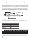
Figure 10. Connecting an HDTV cable box or Satellite
Receiver with Component Video Connections