


3 - 10 3 - 10
MELSEC-Q
3 SPECIFICATIONS
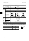
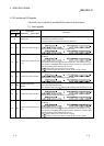
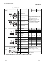
(2) CH Preset value setting (Un\G0, Un\G1, Un\G32, Un\G33)
• This area is used to set the values that are preset in the counter.
• The setting range is between -2147483648 and 2147483647 (32-bit signed
binary).
(3) CH Present value (Un\G2, Un\G3, Un\G34, Un\G35)
• The present values for the counter are stored.
• The stored value range is between -2147483648 and 2147483647 (32-bit
signed binary).
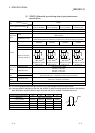
(4) CH Coincidence output point set No.1 (Un\G4, Un\G5, Un\G36,
Un\G37)
CH
Coincidence output point set No.2 (Un\G6, Un\G7, Un\G38,
Un\G39)
• This area is used to write the setting values of the coincidence output points to
be compared with the present counter value.
• Two coincidence detection output points, CH
Coincidence output point set
No.1 (Un\G4, Un\G5, Un\G36, Un\G37) and CH
Coincidence output point set
No.2 (Un\G6, Un\G7, Un\G38, Un\G39), can be set for each channel.
• The setting range is between -2147483648 and 2147483647 (32-bit signed
binary).
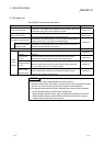
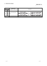
(5) CH Overflow detection flag (Un\G8, Un\G40)
• A counter overflow occurrence status is stored when the counter format is
linear counter.
• The following values corresponding to the overflow occurrence status are
stored in this area.
Condition Buffer memory content
No overflow detection 0
Overflow occurred 1
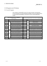
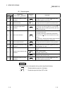
(6) CH Counter function selection setting (Un\G9, Un\G41)
• This area is used to set the data for which a counter function is selected.
• The relationships between the selected counter function and set value are
shown below.
Counter function selection Set value
Count disable function 0
Latch counter function 1
Sampling counter function 2
Periodic pulse counter function 3