


4 - 13 4 - 13
MELSEC-Q
4 SETUP AND PROCEDURE BEFORE STARTING THE OPERATION
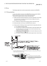
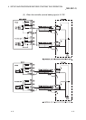
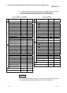
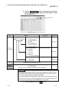
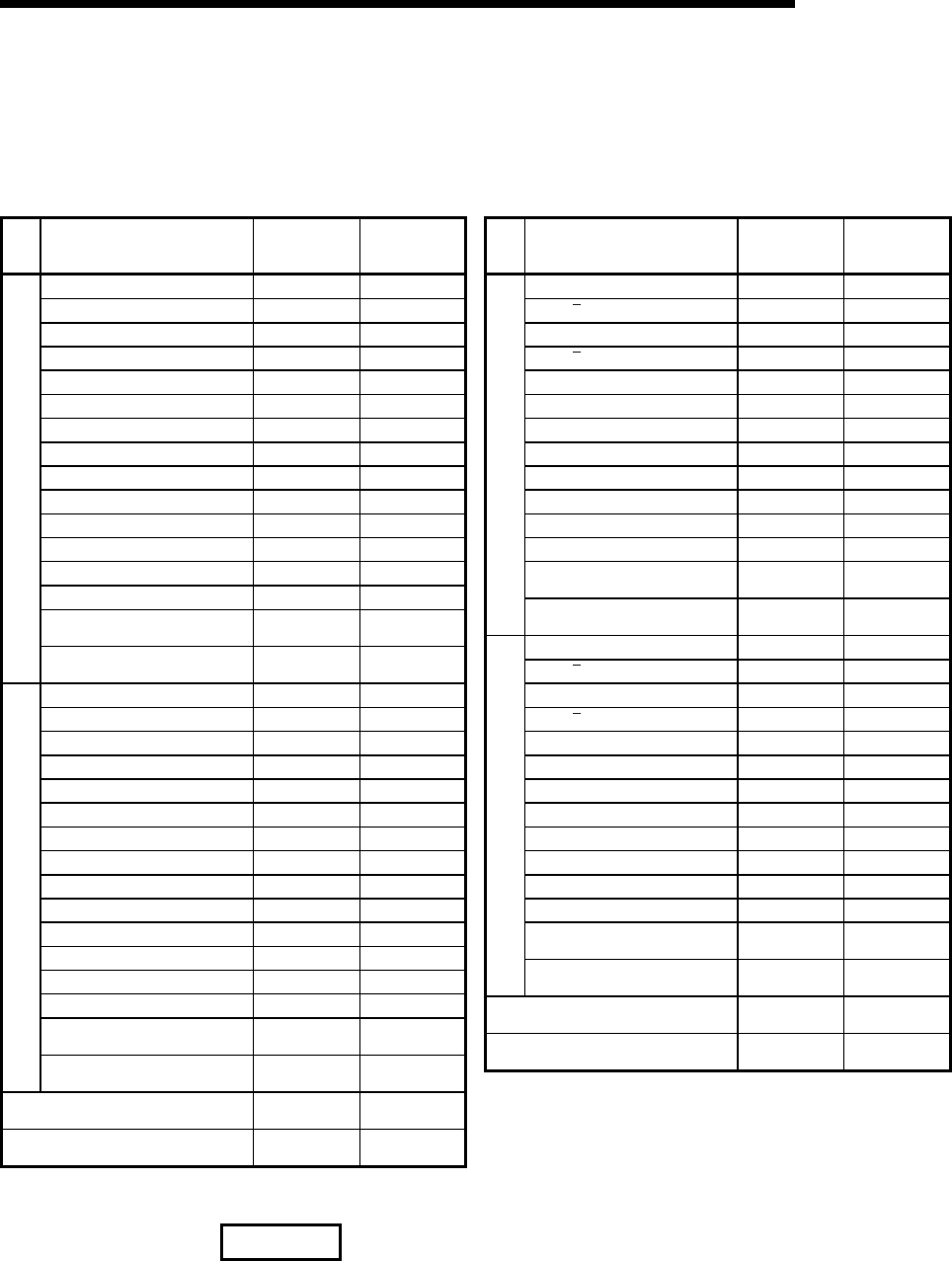
(2) The following table lists the signal names and the corresponding connector side
terminal numbers and terminal block side terminal symbols, when a
connector/terminal block converter module is used in the QD62(E/D) .
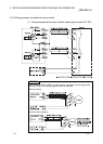
For the QD62 and QD62E
Signal name
Connector side
terminal
number
Terminal block
side terminal
symbol
Phase A pulse input 24 V A20 10
Phase A pulse input 12 V B20 0
Phase A pulse input 5 V A19 11
ABCOM B19 1
Phase B pulse input 24 V A18 12
Phase B pulse input 12 V B18 2
Phase B pulse input 5 V A17 13
Preset input 24 V B17 3
Preset input 12 V A16 14
Preset input 5 V B16 4
CTRLCOM A15 15
Function start input 24 V B15 5
Function start input 12 V A14 16
Function start input 5 V B14 6
EQU1
(Coincidence output point No. 1)
A06 1E
CH1
EQU2
(Coincidence output point No. 2)
B06 E
Phase A pulse input 24 V A13 17
Phase A pulse input 12 V B13 7
Phase A pulse input 5 V A12 18
ABCOM B12 8
Phase B pulse input 24 V A11 19
Phase B pulse input 12 V B11 9
Phase B pulse input 5 V A10 1A
Preset input 24 V B10 A
Preset input 12 V A09 1B
Preset input 5 V B09 B
CTRLCOM A08 1C
Function start input 24 V B08 C
Function start input 12 V A07 1D
Function start input 5 V B07 D
EQU1
(Coincidence output point No. 1)
A05 1F
CH2
EQU2
(Coincidence output point No. 2)
B05 F
12/24 V
B02
B01
24 V
0 V
A02
A01
0 V
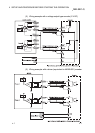
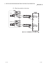
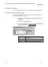
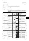
For the QD62D
Signal name
Connector side
terminal
number
Terminal block
side terminal
symbol
Phase A pulse input A20 10
Phase
A
pulse input B20 0
Phase B pulse input A19 11
Phase
B
pulse input B19 1
Preset input 24 V A18 12
Preset input 12 V B18 2
Preset input 5 V A17 13
PRSTCOM B17 3
Function start input 24 V A16 14
Function start input 12 V B16 4
Function start input 5 V A15 15
FUNCCOM B15 5
EQU1
(Coincidence output point No. 1)
A06 1E
CH1
EQU2
(Coincidence output point No. 2)
B06 E
Phase A pulse input A14 16
Phase
A
pulse input B14 6
Phase B pulse input A13 17
Phase
B
pulse input B13 7
Preset input 24 V A12 18
Preset input 12 V B12 8
Preset input 5 V A11 19
PRSTCOM B11 9
Function start input 24 V A10 1A
Function start input 12 V B10 A
Function start input 5 V A09 1B
FUNCCOM B09 B
EQU1
(Coincidence output point No. 1)
A05 1F
CH2
EQU2
(Coincidence output point No. 2)
B05 F
12/24 V
B02
B01
24 V
0 V
A02
A01
0 V
REMARK
If a connector/terminal block converter module is used in the QD62D, the terminals
on the terminal block side with symbols, C, D, 1C and 1D are not used.