


4 - 1 4 - 1
MELSEC-Q
4 SETUP AND PROCEDURE BEFORE STARTING THE OPERATION
4
4 SETUP AND PROCEDURE BEFORE STARTING THE OPERATION
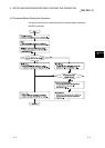
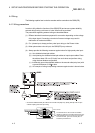
The following describes the procedure prior to the QD62(E/D) operation, the name and
setting of each part of the QD62(E/D), and wiring method.
4.1 Handling Precautions
The following are the precautions for handling the QD62(E/D).
(1) Do not drop the module casing or connector, or do not subject it to strong impact.
(2) Do not remove the PCB of each module from its case. Doing so may cause
breakdowns.
(3) Be careful not to let foreign particles such or wire chips get inside the module.
These may cause fire, breakdowns and malfunctions.
(4) The top surface of the module is covered with a protective film to prevent foreign
objects such as wire chips from entering the module when wiring. Do not remove
this film until the wiring is complete.
Before operating the system, be sure to remove the film to provide adequate heat
ventilation.
(5) Tighten the screws such as module fixing screws within the following ranges.
If the screws are loose, it may cause the module to fallout, short circuits, or
malfunction.
If the screws are tightened too much, it may cause damage to the screw and/or
the module, resulting in fallout, short circuits or malfunction.
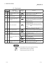
Screw location Tightening torque range
Module fixing screw (M3 screw)*
1
0.36 to 0.48 N · m
Connector screw (M2.6 screw) 0.20 to 0.29 N · m
* 1 The module can be easily fixed onto the base unit using the hook at the top
of the module.
However, it is recommended to secure the module with the module fixing
screw if the module is subject to significant vibration.
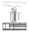
(6) To mount the module on the base unit, fully insert the module fixing latch into the
fixing hole in the base unit and press the module using the hole as a fulcrum.
Improper installation may result in a malfunction or breakdown of the module, or
may cause the module to fall off.