


5 - 3 5 - 3
MELSEC-Q
5 BASIC USAGE
5.1.2 Setting the count method
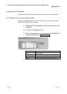
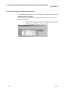
The count method is set using the GX Developer intelligent function module switch
setting.
See Section 4.5 for details on the setting method.
5.1.3 Reading the present values
This section explains the methods of reading the present values stored in the buffer
memory or the count values when counter function selection is executed.
(1) The present value is stored in CH
Present value (Un\G2, Un\G3, Un\G34,
Un\G35) regardless of the counter function used.
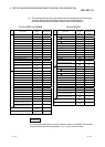
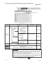
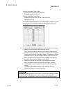
When the latch counter, the sampling counter, or the periodic pulse counter
function is performed, each count value is stored in the buffer memory listed in the
table below.
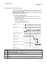
Counter function selection count value
Description
Present
value
Latch count
value
Sampling
count value
Periodic pulse count
previous value
Periodic pulse count
present value
CH1
Un\G2,
Un\G3
Un\G12,
Un\G13
Un\G14,
Un\G15
Un\G16, Un\G17 Un\G18, Un\G19
Buffer
memory
address
CH2
Un\G34,
Un\G35
Un\G44,
Un\G45
Un\G46,
Un\G47
Un\G48, Un\G49 Un\G50, Un\G51
(2) The present value and the counter function selection count values are stored in
the buffer memories in 32-bit signed binary.
The latest count values can be read from the buffer memories because the buffer
memory data are automatically updated by count operation.
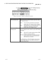
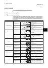
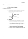
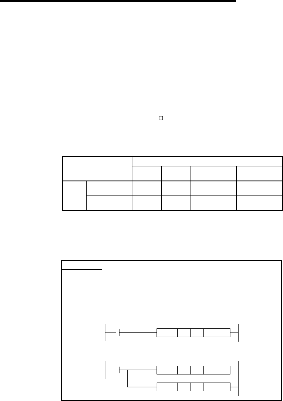
POINT
When reading the present values or the counter function selection count values,
use the DFRO instruction and always read values in two-word units. When reading
the values in one-word units, if the count values are updated in the middle of read
processing, a mismatch may occur between the data contents of the lower and
higher words, possibly causing the system to read incorrect count values.
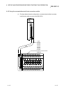
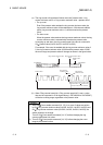
[Program example]
DFRO
H00 H02 D0 K1
X20
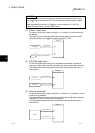
[Example of an undesirable program]
FROM
H00 H03 D1 K1
FROM
H00 H02 D0 K1
X20