139
Chapter 8 Connecting to External Devices
Chapter 8 Connecting to External Devices
Functionality Provided by Connections to USB 2.0 Connector
Connecting to a computer in USB
device mode
A USB 2.0 connection to a computer or other device allows
you to use P2 cards in the camera as mass storage.
Procedures for making connections to a
computer
1
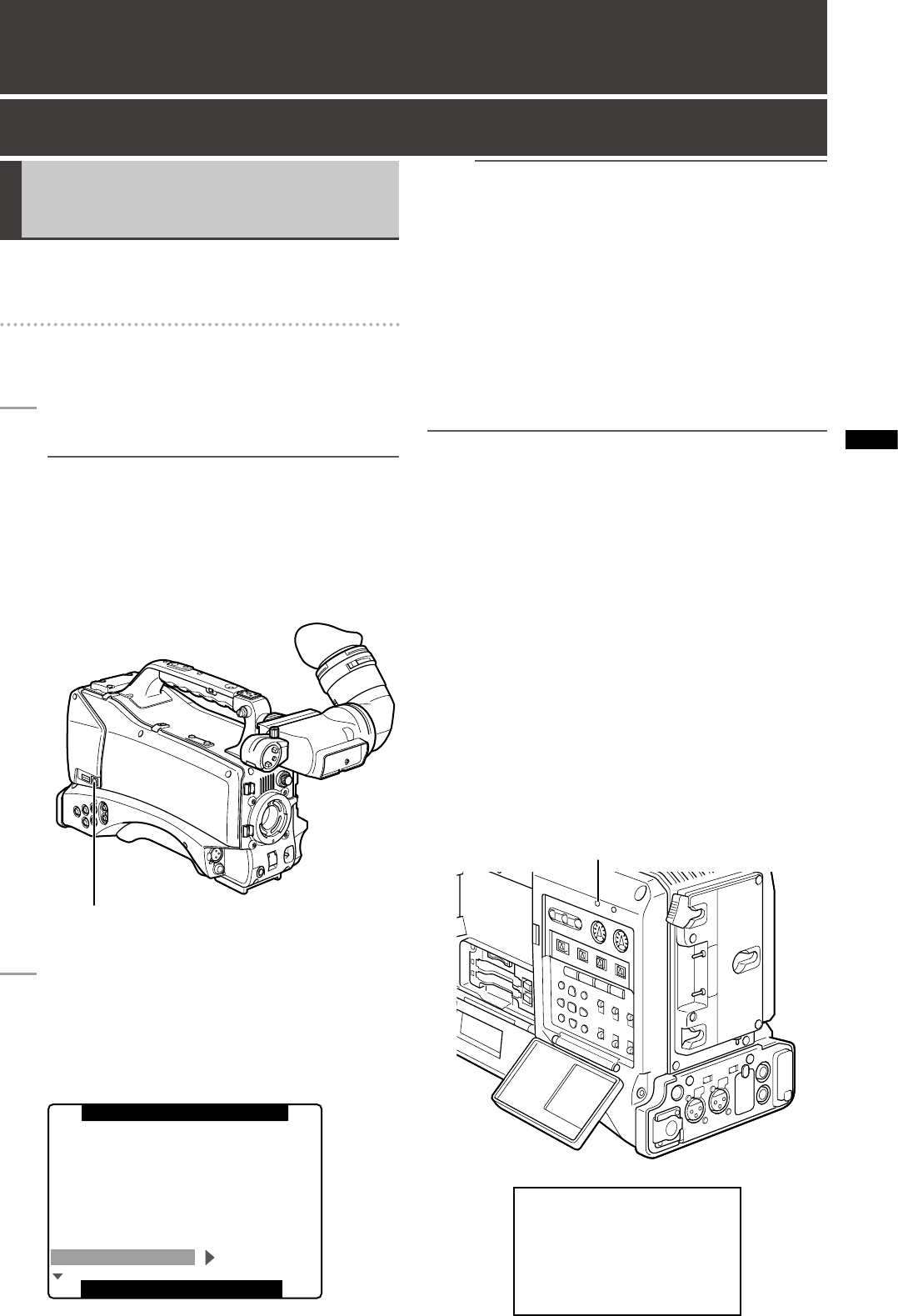
Connect a USB cable to the USB 2.0 connector.
NOTE
• A USB 2.0 cable is not supplied with the AG-HPX300P.
Use a commercially available USB cable (with
shielding or other noise-reduction measures) that
supports USB 2.0.
• The camera supports USB cable lengths up to 5
meters. However, we recommend use of a USB cable
shorter than 3 meters.
USB 2.0 Connector (DEVICE)
2
Set the menu option PC MODE SELECT in the
SYSTEM SETUP screen to USB DEVICE and
set PC MODE to ON.
For details on menu operation, refer to [Using the
menus] (page 120).
PUSH MENU TO EXIT
REC SIGNAL
REC FORMAT
CAMERA MODE
SCAN REVERSE
ASPECT CONV
SETUP
1080-59.94i
CAMERA
AVC-I100/60i
60i
OFF
PC MODE SELECT USB DEVICE
SIDE CROP
0%
SYSTEM MODE
SYSTEM SETUP
NOTE
You can use the menu option USER MAIN/USER1/
USER2 in the SW MODE screen to assign PC MODE
settings to a user button.
Note that the USER button functions are not available
when the menu is open.
To make a USB connection, you must first install the P2
software on the supplied CD-ROM on the computer. Select
the “AG-HPX300” driver. This USB driver supports only
the Windows operating system. For details, refer to the
installation manual.
NOTE
• A USB driver must be installed on the computer.
• Use a computer that supports USB 2.0 since the camera
supports only USB 2.0.
• Connect only one camera to a computer via USB.
• Do not remove P2 cards when the camera is connect to a
computer via USB.
• In a USB connection, the P2 CARD ACCESS LED is on only
when the card is accessed.
• In USB device operation, recording, playback and clip
thumbnail operations are not available.
• When a USB device is running, the remaining capacity of P2
cards is not indicated. Audio is not output through the SDI
OUT or DVCPRO/DV connector and the AUDIO level meters
do not appear.
• The USB lamp on the camera lights during USB
connection and USB DEVICE CONNECT appears in the
center of the viewfinder. If a normal connection cannot
be established, the USB lamp blinks and DISCONNECT
appears in the viewfinder.
USB LED
(Viewfinder display)
USB DEVICE
CONNECT


