12
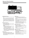
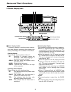
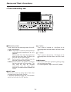
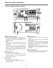
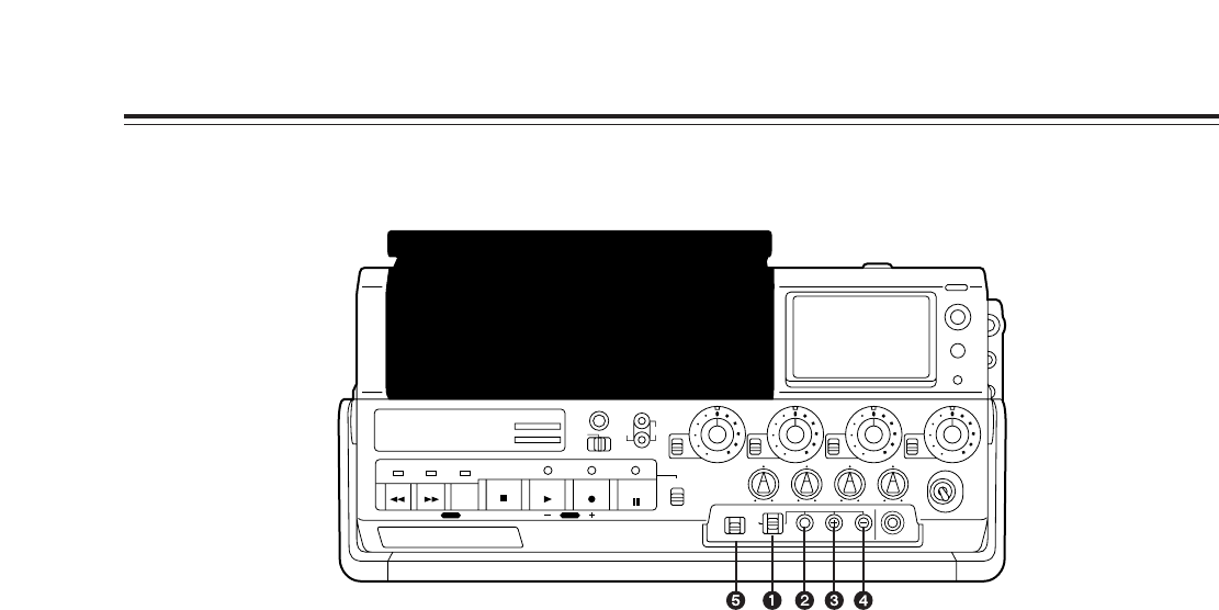
4. Time code setting area
Parts and Their Functions
1
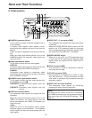
TCG selector switch
This is used to set the advancing mode of the built-
in time code generator.
F-RUN: This position is used to advance the time
code continuously regardless of the unit’s
operation.
Set the switch here when aligning the time
code with the actual time or locking the
time code with an external signal.
SET: Set the switch to this position when the
time code or user’s bit is to be set.
R-RUN: Set the switch to this position to advance
the time code only during recording. The
time code will then be recorded
continuously onto the tape where
continuity has been ensured between the
frames.
2
SHIFT button
This button causes the setting digit to flash when
the time code or user’s bit is to be set.
It becomes operational when the TCG selector
switch has been set to the SET position.
3
“+” button
This is used to increase by 1 the figure for the
setting digit when the time code or user’s bit is to be
set.
4
“–” button
This is used to decrease by 1 the figure for the
setting digit when the time code or user’s bit is to be
set.
5
MENU switch
This is set to SET when performing settings using
the on-screen menu items.
For normal operation, keep it at the OFF position.
RESET
TC
UB
KEY INHIBIT
PAUSE/
STILL
REC
PLAYSTOP
SEARCH
REW
PAGE DOWN MODE SETUP
FF
ON
OFF
UNI
VAR
CH
1
Digital Video Cassette Recorder
AJ-
UNI
VAR
CH
2
UNI
VAR
CH
3
UNI
VAR
ON
OFF
CH
4
CASSETTE IN
METER
LIGHT
WARNING
CH4CH3CH2
SHIFT
REC REVIEW
CH1
PB
LEVEL
CH1 CH2 CH3 CH4
POWER
25 50
CTL
F
-RUN
SET
R
-RUN
MENU DATA
EJECT
M
-cassette
Caution:Do not insert S-cassette or with adaptor
OFF
SET
MENU


