


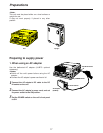
15
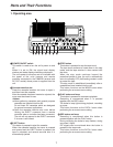
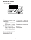
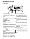
2. Video section
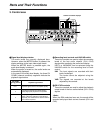
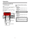
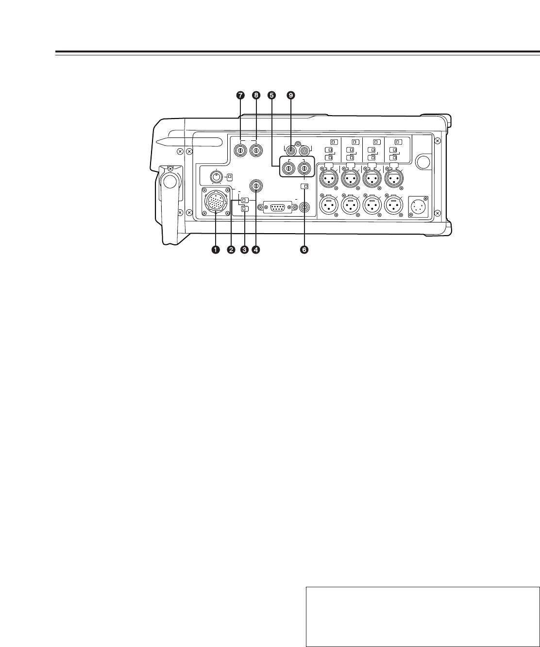
Parts and Their Functions
1
CAMERA connector (26-pin)
This is used to connect a camera equipped with a
multi connector.
It enables video signals, audio signals, control
signals and other signals to be sent to and from the
camera.
Power can also be supplied to the camera from the
unit.
When the video input selector switch is set to the
CAMERA position, the camera’s video signals are
input to the unit.
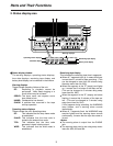
2
Video input selector switch
This is used to select the input video signals.
VIDEO IN:
Composite video signals from the device which has
been connected to the VIDEO IN connector.
CAMERA:
Component video signals or composite video
signals from the camera which has been connected
to the CAMERA connector.
3
CAMERA input signal selector switch
This is used to select the input video signals from
the CAMERA connector
1
.
COMPONENT:
Component video signals from the
camera
COMPOSITE:
Composite video signals from the
camera
4
VIDEO IN connector (BNC)
The composite video signals are supplied to this
connector.
When the video input selector switch is set to the
VIDEO IN position, the video signals from the
device connected to the VIDEO IN connector are
input to the unit.
<Note>
When the unit is in the playback mode, supply
standard signals to this connector. The playback
output signals will then be synchronized with the
input signals.
5
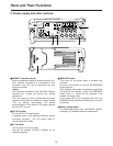
VIDEO OUT 1, 2 connectors (BNC)
The composite video signals are output from these
connectors.
When the SUPER IMPOSE switch is set to the ON
position, the VTR’s operating status or time code
will be superimposed onto the video signals which
are output from the VIDEO OUT 2 connector.
6
SUPER IMPOSE switch
When this is set to ON, the VTR’s operating status
or time code will be superimposed onto the video
signals which are output from the VIDEO OUT 2
connector.
7
TC IN connector (BNC)
This connector is used for recording an external
time code onto the tape.
8
TC OUT connector (BNC)
During playback, the playback time code is output
from this connector. During recording, the time
code which is generated by the internal time code
generator is output.
9
VIDEO OUT connector (PHONO)
The composite video signals for monitoring
purposes are output from this connector.
<Note>
The setup for the VIDEO IN and OUT connectors
and CAMERA connector can be processed using the
setup menu item No. 608 and 609 settings. (See
page 50)
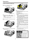
HEADPHONES
EARPHONE
VIDEO IN
REMOTE
DC OUT
... 12V 200mA
SUPER IMPOSE
OFF
ON
PHONE
LEVEL
PHONE
SELECT
TC
IN OUT
VIDEO
OUT
VIDEO
OUT
12
AUDIO
OUT
CH1
·
2
CH1
BREAKER
DC IN
A
U
D
I
O
I
N
A
U
D
I
O
O
U
T
CAMERA
DC ... 12V 3A
COMPO-
NENT
MIC POWER
OFF
CAM LINE
-60
+4dB
ON
CH2
MIC POWER
OFF
CAM LINE
-60
+4dB
ON
CH3
MIC POWER
OFF
CAM LINE
-60
+4dB
ON
CH4
MIC POWER
OFF
CAM LINE
-60
+4dB
ON
COMPO-
SITE
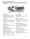
CH3
·
4
CH 1 CH 2 CH 3 CH 4
CH 1 CH 2 CH 3 CH 4
PUSH PUSH PUSH PUSH