


14
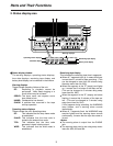
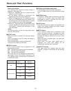
1. Audio section
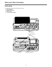
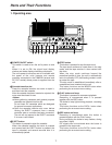
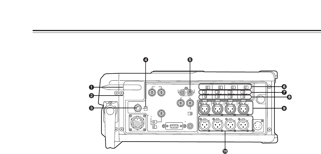
Parts and Their Functions
1
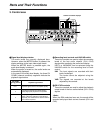
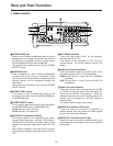
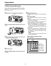
HEADPHONES jack
When a pair of stereo headphones (with an 8-ohm
impedance) are connected to this jack, the sound of
the recording or playback and the warning alarms
can be monitored through the headphones.
The sound to be monitored is set using the PHONE
SELECT switch.
2
EARPHONE jack
When earphones or a pair of stereo headphones
equipped with a mini plug are connected to this
jack, the sound of the recording or playback and the
warning alarms can be monitored through the
earphones.
The sound to be monitored is set using the PHONE
SELECT switch.
3
PHONE LEVEL control
This control is used to adjust the volume of the
sound which is output from the HEADPHONES jack
or EARPHONE jack.
4
PHONE SELECT switch
This is used to select the sound to be monitored at
the HEADPHONES jack or EARPHONE jack.
CH1/2: Sound of CH1 and CH2
CH3/4: Sound of CH3 and CH4
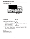
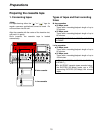
5
AUDIO OUT connectors (PHONO)
The audio signals to be monitored are output
through these connectors. Whether PCM sound or
CUE sound is to be set as the audio output during
playback can selected using setup menu item No.
705.
When PCM is selected, one of six kinds of channel
outputs can be selected using setup menu item No.
731.
6
MIC POWER switches
These turn the power (+48V) for the phantom
microphones ON or OFF.
(The power can be switched to +12V using an
internal switch. For further details, consult your
dealer.)
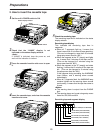
7
Audio input selector switches
These are used to switch the audio inputs of the
four audio channels (CH1—CH4) individually.
CAM: Sound which is input from the CAMERA
connector.
LINE: Sound which is input from the AUDIO IN
connectors.
8
Audio input level switches
These are used to switch the input level to –60 dBu
or +4 dBu to match the level of the sound which is
input from the AUDIO IN connectors. When the
switches have been set to the –60 dBu position, the
setting can be changed to –40 dBu using an
internal switch.
(For further details, consult your dealer.)
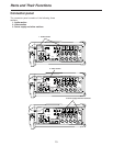
9
AUDIO IN connectors (XLR 3-pin)
These are used to connect a microphone or
external device, and they enable the audio signals
of up to four channels to be input.
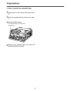
:
AUDIO OUT connectors (XLR 3-pin)
These are used to connect an external device, and
they enable the audio signals of up to four channels
to be output.
HEADPHONES
EARPHONE
VIDEO IN
REMOTE
DC OUT
... 12V 200mA
SUPER IMPOSE
OFF
ON
PHONE
LEVEL
PHONE
SELECT
TC
IN OUT
VIDEO
OUT
VIDEO
OUT
12
AUDIO
OUT
CH1
·
2
CH1
BREAKER
DC IN
A
U
D
I
O
I
N
A
U
D
I
O
O
U
T
CAMERA
DC ... 12V 3A
COMPO-
NENT
MIC POWER
OFF
CAM LINE
-60
+4dB
ON
CH2
MIC POWER
OFF
CAM LINE
-60
+4dB
ON
CH3
MIC POWER
OFF
CAM LINE
-60
+4dB
ON
CH4
MIC POWER
OFF
CAM LINE
-60
+4dB
ON
COMPO-
SITE
CH3
·
4
CH 1 CH 2 CH 3 CH 4
CH 1 CH 2 CH 3 CH 4
PUSH PUSH PUSH PUSH