


29
GETTING STARTED
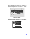
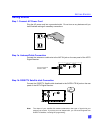
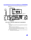
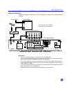
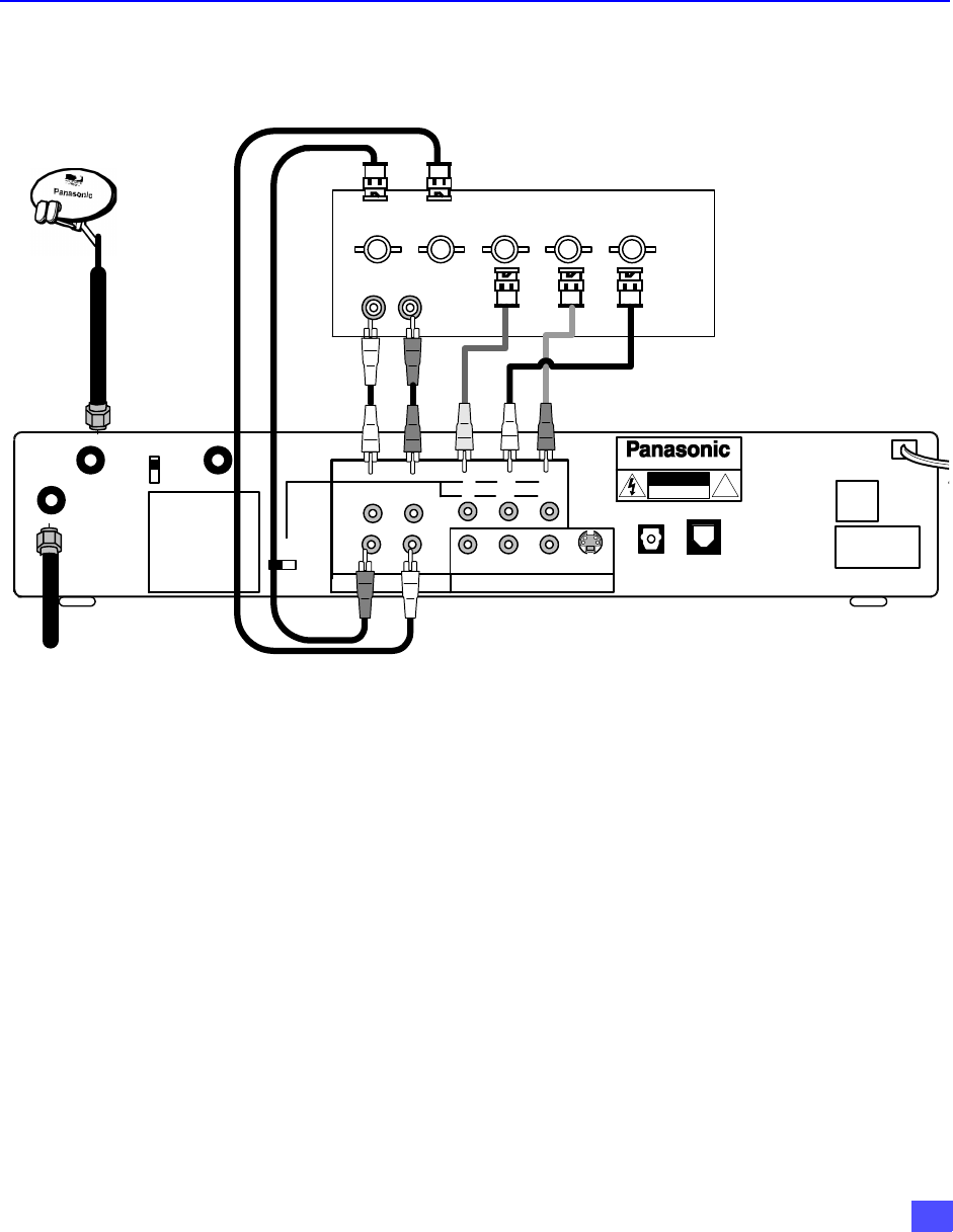
Step 2a. HDTV Digital Receiver Connection to RGB Monitor
Follow this diagram when connecting the HDTV Digital Receiver to a Monitor with
RGB INPUTS.
Procedure
• Connect video cables from the RGB output of the HDTV Digital Receiver to the RGB inputs
of your Monitor.
• Connect the H,V output cables from HDTV Digital Receiver to the H,V inputs of your
Monitor.
• Set the RGB/YP
B
P
R
switch to the RGB position.
• Connect the audio cables from the left and right digital audio output jacks on the HDTV
Digital Receiver to the left and right digital audio jacks on the RGB monitor.
• Select the HDTV Digital Receiver video output according to the capability of your RGB
monitor (Hybrid, Native, 1080i or 720i).
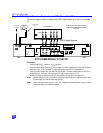
Note: Modem should also be connected to a telephone jack using the supplied modem cable
if impulse pay per view services are desired.
HDTV DIGITAL RECEIVER CONNECTION TO RGB MONITOR
ASSEMBLED IN MEXICO
SATELLITE
IN
DIGITAL
AUDIO OUT
(AC-3)
®
!
WARNING
RISK OF ELECTRIC SHOCK
DO NOT OPEN
HDTV DIGITAL RECEIVER
R-AUDIO-L
CH 3
CH 4
NTSC OUTPUT
R-AUDIO-L VIDEO
S-VIDEO
DIGITAL OUTPUT
H-SYNC-L
R
B G
P
R
P
B
Y
DISTRIBUTED BY
MATSUSHITA ELECTRIC
CORPORATION OF AMERICA
ONE PANASONIC WAY,
SECAUCUS, NEW JERSEY 07094
TEL LINE
MODEL NO.
SERIAL NO.
AC 120V 60Hz
MAX AMPS
MANUFACTURED
RGB/YP
B
P
R
ANT IN
RF OUT
NOTE: RGB cables not
included.
RGB INPUTS
AUDIO
LR
RGB MONITOR
R G BH V
Terrestrial or
Cable Antenna
HDTV DIGITAL RECEIVER