


19
There is a wide range of audio and video equipment that can be connected to your receiver.
The following connection diagrams show you how to connect them.
Note: In case of the monitor in a stand alone situation without the receiver box connected, see the instructions with
the monitor.
Note:
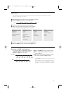
EXT1 can handle CVBS and RGB, EXT2 CVBS, Y/C and RGB, EXT3 and 4 CVBS, EXT5Y-Pb-Br. It is preferred
to connect peripherals with RGB output to
EXT1 or EXT2 as RGB provides a better picture quality.
Note: If your recorder is provided with the EasyLink function, it should be connected to
EXT2 to benefit from the
EasyLink functionality.
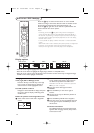
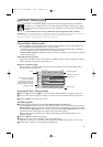
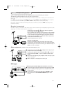
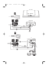
Recorder (VCR
-DVD+RW)
Note: Do not place your recorder too close to the screen as some recorders may be susceptible for signals out of the
display. Keep a minimum distance of 0,5 m to the screen.
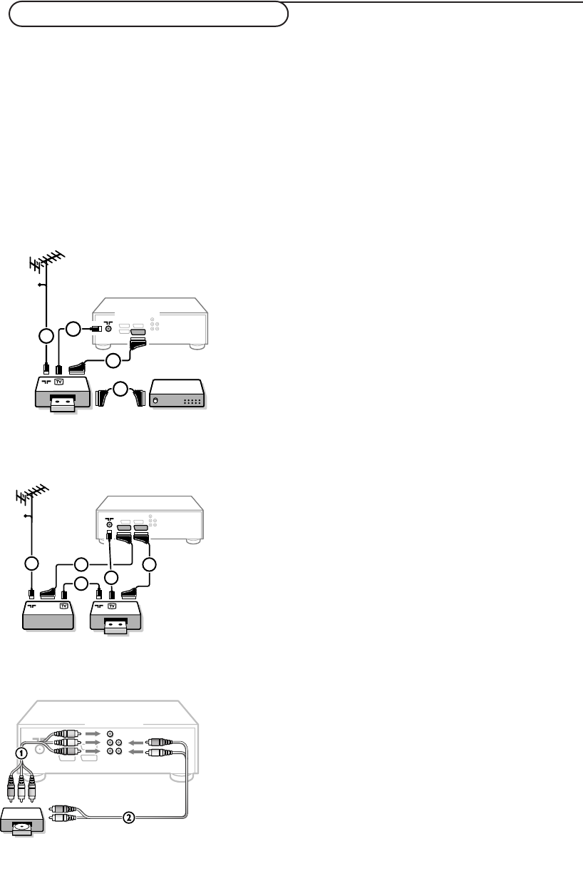
Connect the aerial cables 1, 2 and, to obtain the optimum
picture quality, eurocable 3 as shown.
If your recorder does not have a euroconnector, the only possible
connection is via the aerial cable.You will therefore need to tune
in your recorder’s test signal and assign it programme number 0
or store the test signal under a programme number between 90
and 99, see Manual installation, p. 6.
See the handbook of your recorder.
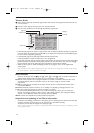
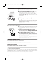
Decoder and Recorder
Connect a eurocable 4 to your decoder and to the special
euroconnector of your recorder. See also the recorder handbook.
See Decoder, p. 10. You can also connect your decoder directly to
EXT1 or 2 with a eurocable.
Other equipment
(satellite receiver, decoder, DVD, games, etc.)
& Connect the aerial cables 1, 2 and 3 as shown (only if your
peripheral has TV aerial in-/output).
Connect your equipment with a eurocable 4 or 5 to one of
the euroconnectors
EXT1, 2, 3 or 4 to obtain a better picture
quality.
é Look for the test signal of your peripheral in the same way as you
do for a recorder.
“ Make a selection in the Setup, Source menu, p. 9.
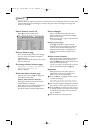
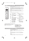
DVD player
With Component Video Output Connectors (EXTERNAL 5)
&
Connect the three separate component video cables to the DVD
player’s
Y, U (Pb) and V (Pr) jacks and to the Y, Pb and Pr jacks
on the receiver.
é Connect the audio cable to the DVD player’s AUDIO L and R
jacks and to the L and R AUDIO EXTERNAL 5 jacks on the
receiver.
VCR 1 DECODER
CABLE
1
EXTERNAL
4
2
3
2
EXTERNAL
21
VCR 1
CABLE
1
5
2
4
3
21
DVD
OUT
EXTERNAL 5
L
RV
U
Y
Connect Peripheral Equipment
1029.2 en 25-03-2003 15:25 Pagina 19