


19
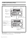
Location and Function of Parts
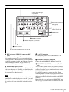
COUNTER SELECT button and the TC SELECT menu
item (see page 68).
Also used to display error messages, edit data, setup menu
data, etc.
j Remote mode indicators
REMOTE: Lights when the Control mode selector is set
to REMOTE to remote control the unit from either an
editing control unit connected to the REMOTE IN (R)/
OUT (P) connectors or equipment connected to the
S400(i.LINK) connector.
9P: Lights when the REMOTE I/F menu item (see page
72) is set to 9PIN.
i.LINK: Lights when the REMOTE I/F menu item (see
page 72) is set to i.LINK.
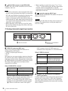
k VITC indicator
Lights when VITC is being read or recorded regardless of
the data shown in the time counter display.
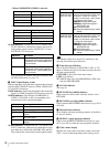
l PB Fs (playback audio sampling frequency) display
During playback, this indicates the playback audio mode
in which the disk being played back was recorded.
48K indicator: Lights during playback of material
recorded in 2-channel mode (48 kHz).
32K indicator: Lights during playback of material
recorded in 4-channel mode (32 kHz).
m REC MODE (audio recording mode) display
This indicates the audio recording mode currently selected
with the REC MODE menu item (see page 71).
2CH indicator: Lights in 2-channel mode (48 kHz).
4CH indicator: Lights in 4-channel mode (32 kHz).
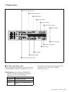
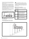
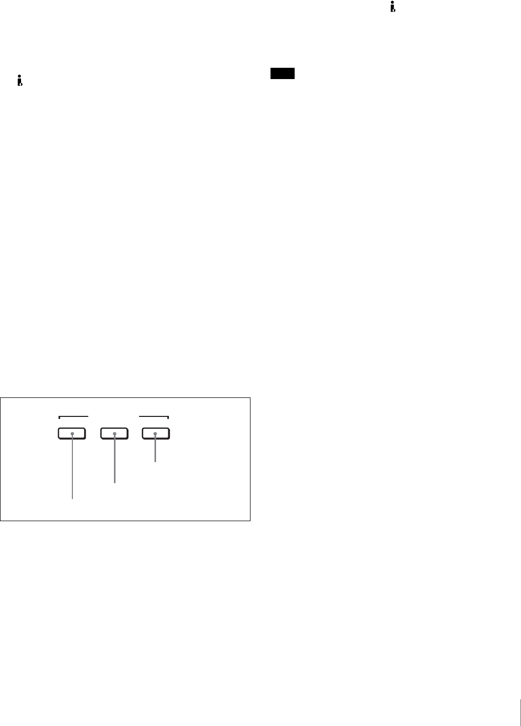
2 Video/audio input setting section
a VIDEO button
Each press of this button cycles through the following
input video signal selection options.
• Composite video signal input to the VIDEO IN
connector
• S-video (separated Y and C) signals input to the VIDEO
IN connectors
•Y, R
−Y and B−Y component video signals input to the
VIDEO IN connectors
• SDI video signal input to the SDI IN connector
• Video test signal (selected with the INT VIDEO SG
menu item (see page 69) generated by the internal signal
generator
• Digital video/audio signal (DV format, complied with
i.LINK) connected to the S400(i.LINK) connector
The selection made with this button is indicated by the
VIDEO indicators in the INPUT signal display section (see
page 18).
Note
When the video input is set to the i.LINK, pressing either
the CH1 1/2 button or CH2 3/4 button changes the setting
to COMPOSITE. Reset the video input.
b CH1 1/2 (audio channel 1 or 1/2) button
Each press of this button cycles through the following
input audio signal selection options for audio channel 1
(when in 2-channel mode) or for audio channels 1 and 2
(when in 4-channel mode).
• Analog audio signal input to the AUDIO IN 1/3
connector
• Digital audio signal in AES/EBU format input to the
AUDIO (AES/EBU) IN 1/2 connector
• SDI audio signal input to the SDI IN connector
• Audio test signal (selected with the INT AUDIO SG
menu item (see page 72) generated by the internal signal
generator
The selection made with this button is indicated by the
AUDIO CH-1 1/2 indicators in the INPUT signal display
section (see page 18).
When analog audio is selected, the signal input to the
AUDIO IN 1/3 connector is recorded either on channel 1
(when in 2-channel mode) or on channels 1 and 3 (when in
4-channel mode). That is, in 4-channel mode, the same
analog audio signal is recorded on channels 1 and 3. Using
the REC/PB LEVEL control knobs with the VARIABLE
switch set to REC, it is possible to adjust the audio levels
on the two channels separately.
You can switch the audio recording mode with the REC
MODE menu item (see page 71). The selection is indicated
by the REC MODE display on the front panel.
c CH2 3/4 (audio channel 2 or 3/4) button
Each press of this button cycles through the following
input audio signal selection options for audio channel 2
(when in 2-channel mode) or for audio channels 3 and 4
(when in 4-channel mode).
• Analog audio signal input to the AUDIO IN 2/4
connector
• Digital audio signal in AES/EBU format input to the
AUDIO (AES/EBU) IN 3/4 connector
• SDI audio signal input to the SDI IN connector
• Audio test signal (selected with the INT AUDIO SG
menu item (see page 72) generated by the internal signal
generator
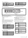
CH1 1/2 CH2 3/4
INPUT SELECT
3 CH2 3/4 button
2 CH1 1/2 button
1 VIDEO button