


8 Chapter 1 Overview
Chapter 1 Overview
Location and Function of Parts
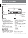
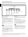
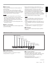
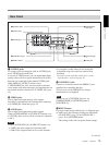
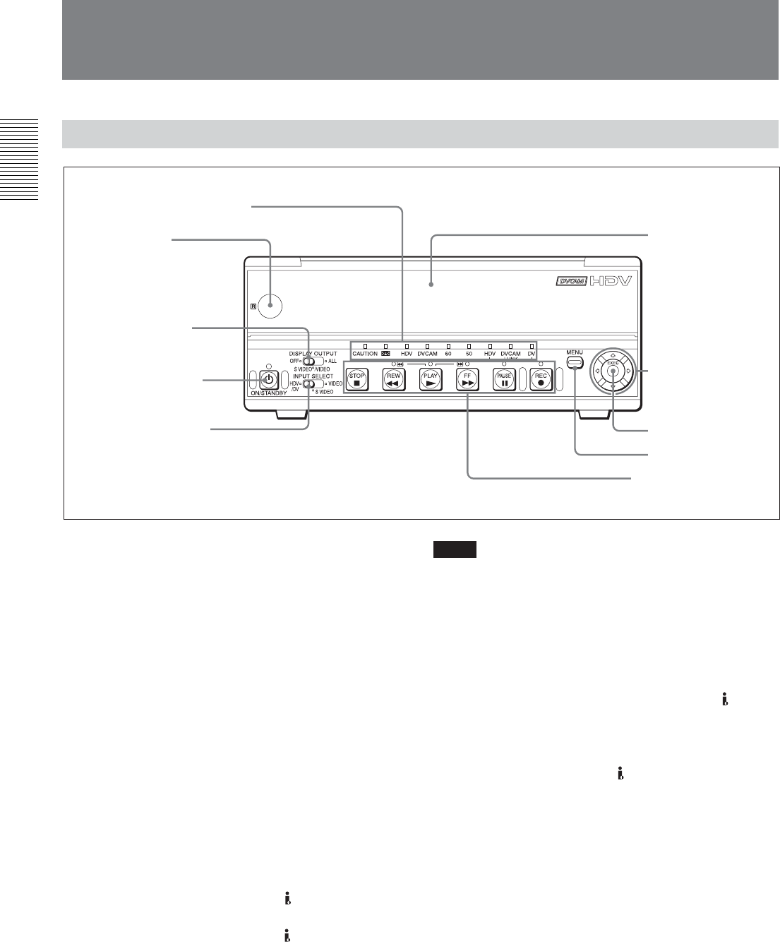
Front Panel
1 Remote sensor
2 DISPLAY OUTPUT switch
Selects the destination for the text data to be
superimposed via output jacks.
OFF : Does not superimpose text data to output.
S VIDEO/VIDEO : Superimposes text data to S
VIDEO OUT jack and VIDEO OUT jack.
ALL : Superimposes text data to COMPONENT
OUT jacks, S VIDEO OUT jack, and VIDEO
OUT jack.
3 ON/STANDBY switch and lamp
Press this switch to turn the unit on, and the ON/
STANDBY lamp lights up in green. When you press
this switch again, the unit goes into STANDBY mode
and the lamp lights up in red.
4 INPUT SELECT switch
Switches the signal input jack from
HDV/DV jack,
S VIDEO jack, and VIDEO jack.
HDV/DV : Inputs a signal from
HDV/DV jack.
S VIDEO : Inputs a signal from S VIDEO jack.
VIDEO : Inputs a signal from VIDEO jack.
Notes
•Do not change the setting of this switch while
recording in progress, or it causes noise added to
images and sounds. Also, a part of the tape where the
change of setting applied will not be recorded
properly. Also, the time code may operate
discontinuously.
• If you change the setting of this switch while
recording in progress, the output signal from
HDV/
DV jack may be interrupted. Also, the unit may detect
signals such as a copyright information signal
incorrectly.
•When a signal is input from
HDV/DV jack, the
settings of the menu listed below are unavailable.
– 60i/50i SEL
– AUDIO MODE
– AUDIO LOCK
– AUDIO AGC
– AUDIO REC LV
5 Cassette Lid
Open this lid to insert or eject a cassette.
For details of usable cassettes, see “Notes on Power Supply
and Video Cassettes” on page 20.
For details of inserting or ejecting a cassette, see “Inserting/
Ejecting Cassettes” on page 21.
1Tape transport control
section
(see page 10)
1 Remote sensor
2 DISPLAY OUTPUT
switch
3 ON/STANDBY switch
and lamp
4 INPUT SELECT switch
5 Cassette Lid
6 J/j/K/k button
7 EXEC (execute)
button
8 MENU button
2 Indicator section
(see page 11)