


Chapter 2 Location and Function of Parts
2-2 Chapter 2 Location and Function of Parts
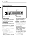
4 Remote control detector
Receives the infrared signal from the supplied Remote
Commander. For details, see “4-4 Using the Remote
Commander” on page 4-7.
5 PF-1/2 (PROGRAMMABLE FUNCTION-1/2)
button
You can assign the function that is set in PF2 KEY
SELECT, basic menu item 022 of the setup menu, to
the PF-2 button. “Tape Remain Time” is assigned to
the PF-2 button as the factory default setting.
While you are pressing the PF-1 or PF-2 button, the
system frequency in playback or the remaining tape
time is displayed in the FL display according to the
button that is being pressed.
For details of the assignment, see “Menu bank operations
(menu items B01 to B12)” on page 5-5.
6 PHONES (headphones) jack and control knob
Connect stereo headphones with an impedance of
8 ohms to monitor the sound during playback.
The control knob adjusts the volume.
It is possible to make a setting so that the output
volume from the AUDIO MONITOR connectors is
controlled simultaneously.
Set AUDIO MONITOR OUTPUT LEVEL, extended
menu item 114, on “VAR” to enable the above feature.
..........................................................................................................................................................................................................
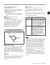
1) LTC: abbreviation of Longitudinal Time code. This
time code is recorded on a longitudinal track on the tape.
Reading is unreliable at low speeds, and not possible at
all during still playback.
2) VITC: abbreviation of Vertical Interval Time code.
This time code is inserted in the vertical blanking
interval and recorded on the video tracks.
1 LTC/VITC button
This selects the time code displayed in the FL display
in the following sequence: LTC
1)
, VITC
2)
. The
underline for the LTC or VITC time code setting
indicators lights corresponding to the selection.
Note
In this unit, VITC may not be displayed correctly
except during normal playback.
2 SET/MENU button
Use this button for setup menu operations and settings.
Press the SET/MENU button while holding down the
SHIFT button to display the contents of the setup
menu items on the FL display. When the setting is
finished, press only the SET/MENU button to fix the
settings and return to the normal display.
For details of setup menu settings and operations, see
Chapter 5, “Setup Menu.”
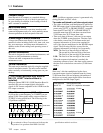
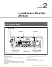
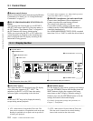
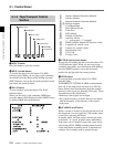
2-1-1 Display Section
1 LTC/VITC button
2 SET/MENU button
3 AU MON SEL button
4 SHIFT button
5 CTL/TC/UB button
6 CTL RESET button
7 FL (Fluorescent) display and indicators
2-1 Control Panel
This illustration shows the J-H3.