


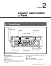

Chapter 2 Location and Function of Parts
2-8 Chapter 2 Location and Function of Parts
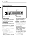
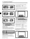
DV (i.LINK DV output ) connector (IEEE1394
type, 6-pin) (available only when an HKJ-101
i.LINK Interface Board (not supplied) is
installed):
This is a connector located on the optional
HKJ-101 i.LINK Interface Board. Outputs video/
audio signals in DV format.
Notes
• Through the DV connector, only one DV
device can be connected to this unit. If you
intend to connect multiple DV devices, refer to
the manuals of them.
• The i.LINK (DV) output of this unit is used to
provide materials to a computer on which non-
linear editing software is installed. You can use
a Sony VTR equiped with an i.LINK (DV)
connector with this unit, though, the auto
dubbing function and editing function will not
be available.
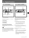
HD (HD output) connectors
COMPONENT (Y/Pb/Pr) connectors (BNC type
×3): Output analog HD component video signals
(Y/Pb/Pr).
D3 output connector: Outputs analog HD
component video signals (Y/Pb/Pr).
MONITOR connector (D-sub 15-pin): Outputs
video signals using the XGA system. The monitor
and projector of the signal receiver should be set
to XGA.
HD SDI (SUPER) (HD serial digital interface
output) connector (BNC type ×1) (J-H3 only):
Outputs video/audio signals in HD format.
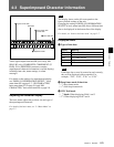
When basic menu item 005, “DISPLAY
INFORMATION SELECT,” of the setup menu is set
to anything other than OFF, the connector outputs
superimposed character information such as time
code, menu settings, or alarm messages.
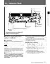
2-2 Connector Panel
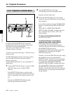
6 AUDIO MONITOR OUTPUT connectors
Audio monitor (L/R) output connectors (XLR
3-pin, male):
Outputs two (L and R) audio monitor signals
according to the setting of the AU MON SEL
button on the control panel.
Audio monitor (L/R) output connectors (Phono
jack ×2):
Outputs two (L and R) audio monitor signals
according to the setting of the AU MON SEL
button on the control panel.
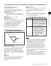
7 EXT SYNC (reference video signal input)
connectors (BNC type ×2) (J-H3 only):
Input reference video signals.
These connectors input the positive/negative
bipolarity ternary sync signal and the Video Burst
Sync (VBS) signal, in other words, the composite
video signal including chroma burst. They also input
the Video Sync (VS) signal, that is, the composite
monochrome video signal. When a bridge connection
is made, the terminator is automatically set to OFF
(75 Ω).
Note
This unit performs on SYNC LOCK. It does not
perform on burst LOCK.