


Chapter 2 Location and Function of Parts
2-4 Chapter 2 Location and Function of Parts
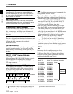
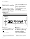
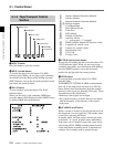
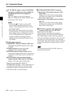
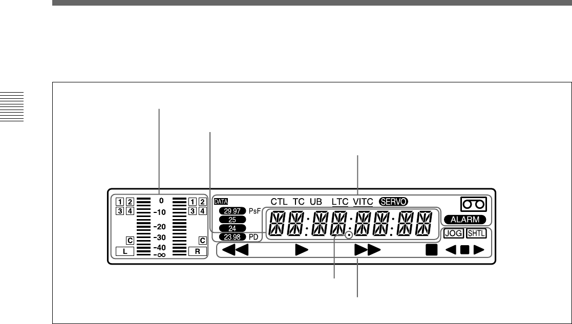
Audio monitor display area
Time data display area
Indicator area
Tape transport indicator area
Audio monitor display area
• L/R audio level meter
Indicates the audio levels of the 2 optionally selected
channels making up L/R (Left/Right).
• L/R audio channel display
Indicates the optionally selected channel numbers.
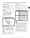
Time data display area
Normally this displays a CTL count, time code value,
or user bit value according to the selection of the CTL/
TC/UB button or LTC/VITC button. When a cassette
recorded in the DF mode is played back, the dot by the
❉ mark in the illustration above lights. At this time, the
two dots (:) located above the dot disappear.
It is also used to display error messages and the setup
menus.
For details of the display of the CTL count, time code value,
or user bit value, see the explanation given in “CTL/TC/UB
(display switching) button” on page 2-3.
Indicator area
This includes the following indicators.
• CTL, TC, UB indicators: The time data selected
using the CTL/TC/UB (display switching) button
lights. Selected time data will be displayed on the
time data display area.
• LTC, VITC indicators: Regardless of the display
in the time data display area, these indicators light
when the corresponding time code values are
being read.
When LTC has been selected using the LTC/VITC
button, the LTC indicator is displayed and
underlined. On the other hand, when VITC is
selected, the VITC indicator is displayed and
underlined.
• SERVO indicator: This lights when the servo lock
is functioning.
• ALARM indicator: This lights when a hardware
error is detected on the unit, and goes off when the
error is resolved. When this indicator is lit, an
error message appears in the time data display
area.
• Cassette-in indicator q: This lights when a
cassette is loaded in the unit.
• DATA indicator: This lights when a tape,
containing audio data such as Dolby-E and AC-3
on its DIGITAL AUDIO track, is played back.
• PsF indicator: This lights when a tape, which is
recorded in PsF, is played back.
• System frequency indicator: The system
frequency selected in SYSTEM FREQUENCY
SELECT, basic menu item 013 of the setup menu,
lights. When the selected frequency and the
frequency of the tape being played back are
incompatible, this indicator flashes.
• PD indicator (J-H3 only): This lights when the
system frequency is set to 23.98PD.
❉
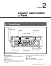
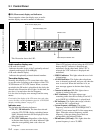
2-1 Control Panel
This illustration shows the J-H3.
7 FL (Fluorescent) display and indicators
These comprise a time data display area, an audio
monitor display area and a number of indicators.