


Chapter 2 Location and Function of Parts
Chapter 2 Location and Function of Parts 2-7
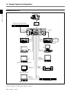
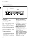
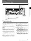
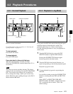
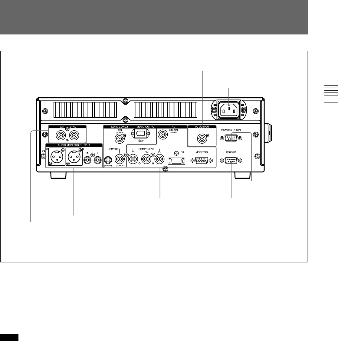
2-2 Connector Panel
1 TC OUTPUT connector
1 TC OUTPUT (time code output) connector
(BNC type ×1) (J-H3 only):
Outputs the playback time code.
2 AC IN connector
Connects to an AC outlet using the power cord (not
supplied).
Notes
• Place the unit near the AC outlet for easier reach of
the breaker.
•Make sure to perform a ground connection for the
unit before you plug the unit into the wall outlet. If
you disconnect the grounding, unplug the unit from
the wall outlet first.
3 REMOTE IN (9P) (remote control signal input)
connector (D-sub 9-pin, female) (J-H3 only):
Connects to a BVE series editor or other VTR using a
9-pin remote control cable (not supplied) to externally
control the unit.
4 RS-232C (RS-232C serial interface) connector
(D-sub 9-pin, male)
Exchanges the RS-232C serial remote control signal
and the VTR status signal with external devices such
as a computer installed JZ-1.
5 VIDEO OUTPUT connectors
SD (D CONV.) (SD output) connectors
COMPOSITE (SUPER) (analog composite video
output) connector (Phono jack ×1): Outputs an
analog composite video signal.
COMPOSITE (SUPER) (analog composite video
output) connector (BNC type ×1): Outputs an
analog composite video signal.
SDI (SUPER) (serial digital interface output)
connector (BNC type ×1) (J-H3 only): Outputs
video/audio signals in D1 format.
4 RS-232C connector
5 VIDEO OUTPUT
connectors
6 AUDIO MONITOR OUTPUT connectors
2 AC IN connector
3 REMOTE IN
connector
7 EXT SYNC
connectors
This illustration shows the J-H3 equipped with
an HKJ-101 i.LINK Interface Board.