


Chapter 5 Setup Menu
Chapter 5 Setup Menu 5-7
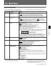
5-3 Basic Menu
The basic menu contains the following items.
In the “Settings” column of the table, the factory
a) When setting items 002, 003 and 009, watch the monitor
screen, and adjust to the required state.
Item number Item name Settings
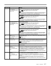
002
a)
CHARACTER H-
POSITION
Adjusts the horizontal screen position of the character information output from the
VIDEO OUTPUT connectors for superimposed display on the monitor.
0 ... 4 ... 8: The value 0 is for the far left of the screen and 8 for the far right.
Increasing the value moves the position of the characters to the right.
003
a), b)
CHARACTER V-
POSITION
Adjusts the vertical screen position of the first line of the character information
output from the VIDEO OUTPUT connectors for superimposed display on the
monitor.
0 ... 13 ... 16 (29.97/23.98PD system (J-H3 only))/0 ... 14 ... 17 (25/24 (J-H3
only) /23.98 system (J-H3 only)): The value 0 is for the top of the screen and
increasing the value lowers the position of the characters.
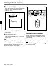
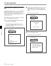
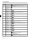
005 DISPLAY INFORMATION
SELECT
Determines the kind of character information to be output from the VIDEO
OUTPUT connectors.
OFF : Displays no character information.
T&STA : Time data display information and the unit’s status
T&UB: Time data display information and the user bits
T&CTL: Time data display information and CTL
T&T: Time data display information and time code (LTC or VITC)
TIME: Time data display information only
When the system frequency is set to 23.98PD, 29.97-frame time code and 23.98-
frame time code are displayed in two rows as shown below (J-H3 only).
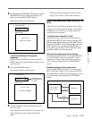
If there is an overlap between the setting of this item and the character
information selected by the setting of the control panel, output of the overlapped
information is automatically avoided. For example, if CTL is selected on the
control panel and this menu item setting is T&CTL, CTL and LTC will be output.
default settings are indicated by an enclosing box.
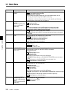
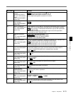
007 TAPE TIMER DISPLAY
Determines whether to display the CTL counter in 12-hour mode or 24-hour mode.
+ –12H : 12-hour mode
24H: 24-hour mode
b) When displaying time code values, there is a slight time
delay. Therefore, when creating a tape for off-line
editing, the information inserted in the upper half of the
screen may be delayed by one frame.
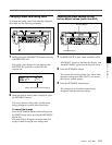
012 CONDITION DISPLAY ON
VIDEO MONITOR
Determines whether or not to display the channel status in addition to the
characters being superimposed.
DIS : Disables display.
ENA: Enables display.
Displayed channel status
The channel statuses are displayed under the timer or status display line.
e.g. V — A —
The letters that follow “V” indicate the status of the video channels of the rotation
head.
The letters that follow “A” indicate the status of the audio channels of the rotation
head.
Character patterns
–: Good condition
*: Acceptable condition
x: Bad condition
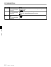
009
a)
CHARACTER TYPE Determines the type of characters, such as time code, output from the VIDEO
OUTPUT connectors for superimposed display on the monitor.
WHITE : White letters on a black background
BLACK: Black letters on a white background
W/OUT: White letters with black outlines
B/OUT: Black letters with white outlines
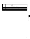
Items in the basic menu
29.97-frame time code
23.98-frame time code