


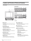
Location and Function of Parts and Controls
17
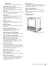
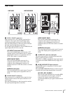
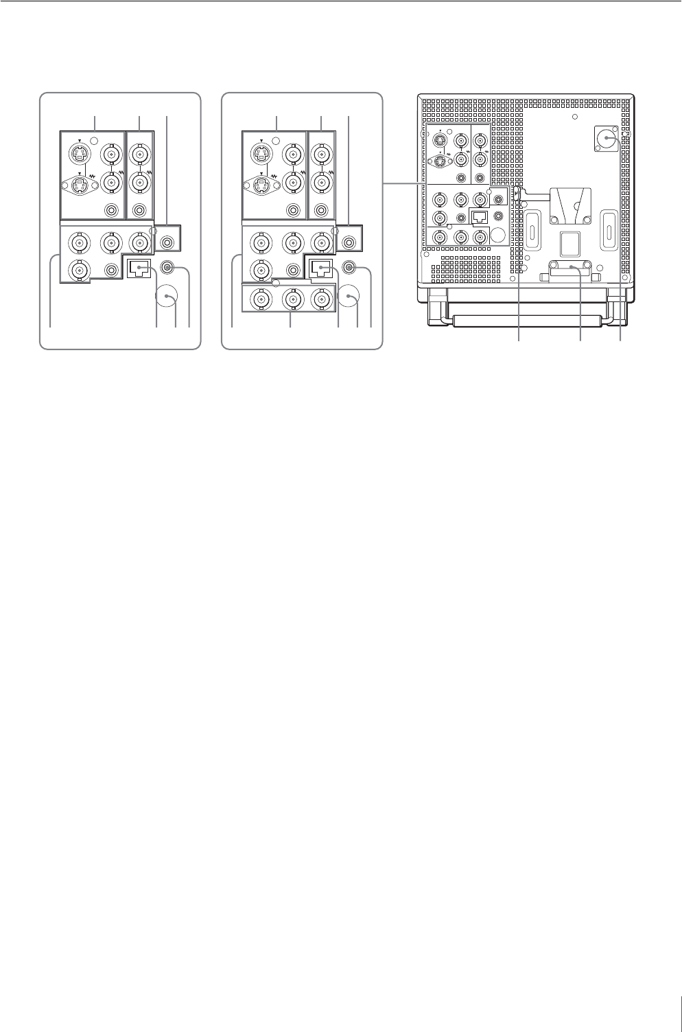
Rear Panel
a LINE A IN/OUT connectors
Input connectors for a Y/C separate signal and for a
composite video signal, their loop-through output
connectors and input connector for an audio signal.
Press the LINE A button on the front panel to monitor
the input signal through these connectors.
If you input signals to both Y/C IN and VIDEO IN, the
signal input to the Y/C IN is selected.
Y/C IN/OUT (4-pin mini-DIN)
These are the input/output connectors for a Y/C
separate signal. Connect them to the Y/C separate
input/output connectors on equipment such as a
VCR, video camera, or another monitor.
VIDEO IN/OUT (BNC)
These are the input/output connectors for a
composite video signal. Connect them to the
composite video input/output connectors on
equipment such as a VCR, video camera, or another
monitor.
AUDIO IN (mini jack)
This is the input jack for an audio signal. Connect it
to the audio output jack on equipment such as a
VCR.
b LINE B IN/OUT connectors
Input connector for a composite video signal, its loop-
through output connector and input connector for an
audio signal.
Press the LINE B button on the front panel to monitor
the signal input through these connectors.
VIDEO IN/OUT (BNC)
These are the input/output connectors for a
composite video signal. Connect them to the
composite video input/output connectors on
equipment such as a VCR, video camera, or another
monitor.
AUDIO IN (mini jack)
This is the input jack for an audio signal. Connect it
to the audio output jack on equipment such as a
VCR.
c AUDIO OUT connector (mini jack)
The audio signal which is selected by the input select
button on the front panel is output.
When SDI-1 or SDI-2 is selected, the input signal which
is selected in the USER CONFIG menu (on page 26) is
output.
d RGB/COMPONENT input connectors
Analog RGB signal or component (Y, P
B, PR) signal
input connectors.
Press the RGB/COMPONENT button on the front panel
to monitor the signal input through these connectors.
G/Y, B/P
B, R/PR IN (BNC)
These are the input connectors for an analog RGB
and a component (Y, P
B, PR) signal. Unless an
external sync signal is input, the monitor is
synchronized with the sync signal contained in the
G/Y signal.
LINE A
Y/C
IN
IN
IN
IN IN
OUT
VIDEO
RGB/COMPONENT
B/PBG/Y
EXT SYNC
IN-1 IN-2
SDI(HD/D1-SDI)
MONITOR OUT
PARALLEL REMOTE
AUDIO IN
AUDI O
AUDIO OUT
HEADPHONES
i
R/PR
IN
VIDEO
AUDIO IN AUDIO IN
IN
OUT OUT
LINE B
LINE A
Y/C
IN
IN
IN
IN IN
OUT
VIDEO
RGB/COMPONENT
B/PBG/Y
EXT SYNC
IN-1 IN-2
SDI(HD/D1-SDI)
MONITOR OUT
PARALLEL REMOTE
AUDIO IN
AUDIO
AUDIO OUT
HEADPHONES
i
R/PR
IN
VIDEO
AUDIO IN AUDIO IN
IN
OUT OUT
LINE B
LINE A
Y/C
IN
IN
IN
IN IN
OUT
VIDEO
RGB/COMPONENT
B/PBG/Y
EXT SYNC
PARALLEL REMOTE
AUDIO IN
AUDIO
AUDIO OUT
HEADPHONES
i
R/PR
IN
VIDEO
AUDIO IN AUDIO IN
IN
OUT OUT
LINE B
0q
a
9
5786
1
2 3
4786
1
2 3
4
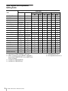
LMD-9050/9030LMD-9020
*
1