


Installing and Connecting the LCD Projection TV
23
Installing and Connecting the LCD Projection TV
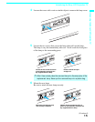
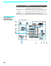
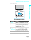
Connection Description
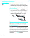
1 VHF/UHF Connects to your VHF/UHF antenna or cable box output
jack.
2 CABLE Connects to your cable signal. This CABLE input jack, in
conjunction with the VHF/UHF input jack, lets you set up
your LCD projection TV to switch between scrambled
channels (coming through a cable box) and unscrambled
cable channels. For details, see page 28.
3 i.LINK Connects to i.LINK-compatible devices. These terminals
are not intended for connection with personal computers.
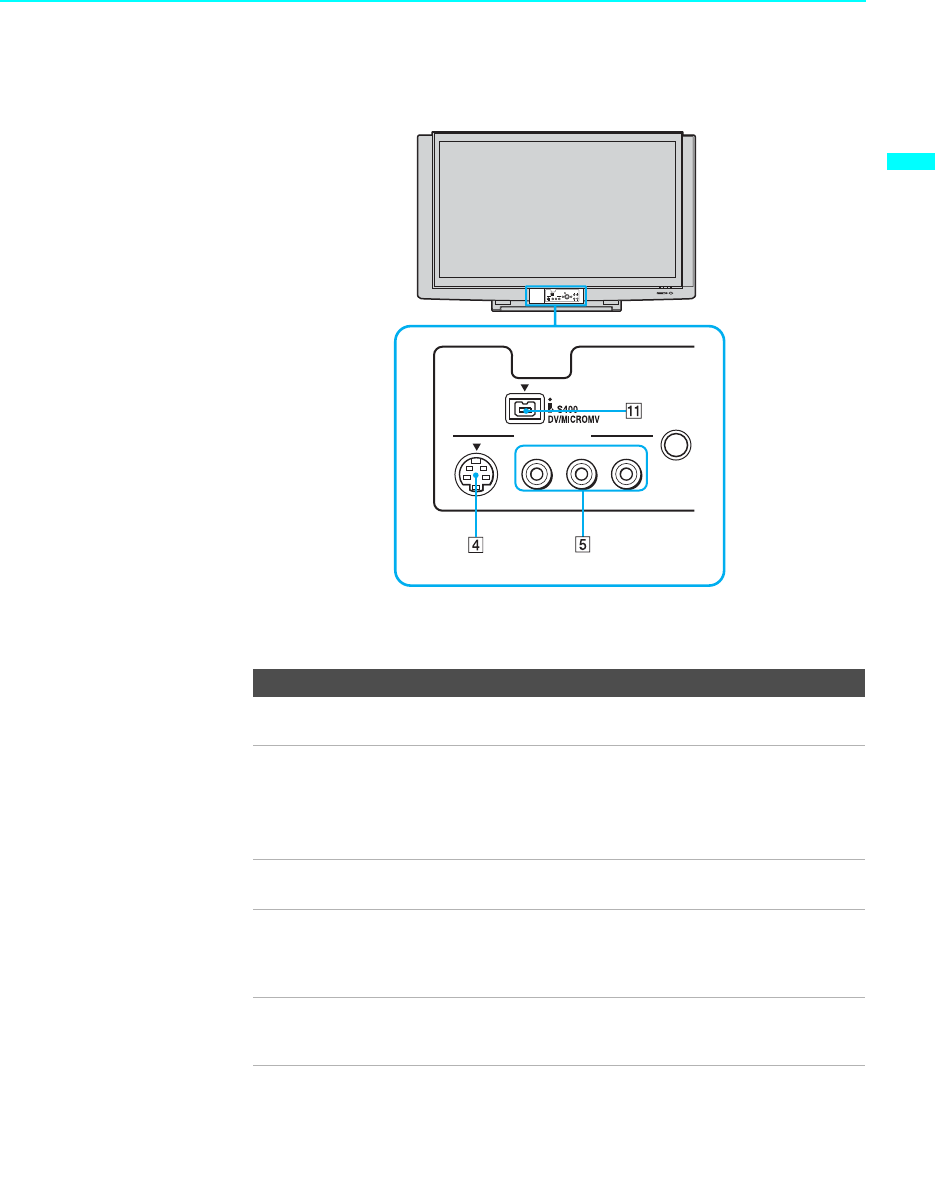
4 S VIDEO
(Front and rear)
Connects to the S VIDEO OUT jack of your VCR or other
S VIDEO-equipped video component. Provides better
picture quality than the VHF/UHF jacks or the Video IN
jack.
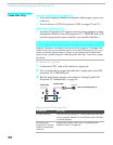
5 VIDEO/
(L/R) AUDIO
(Front and rear)
Connects to the audio and video OUT jacks on your VCR
or other video component. A fourth video input (VIDEO 2)
is located on the front panel of the LCD projection TV.
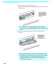
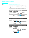
MENU
S VIDEO
VIDEO
(MONO)
L–AUDIO–R
VIDEO 2 IN
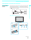
Front Panel of LCD projection TV
Front panel connectors are in the control panel
cover. To open and close the cover, refer to page 21.
(Continued)